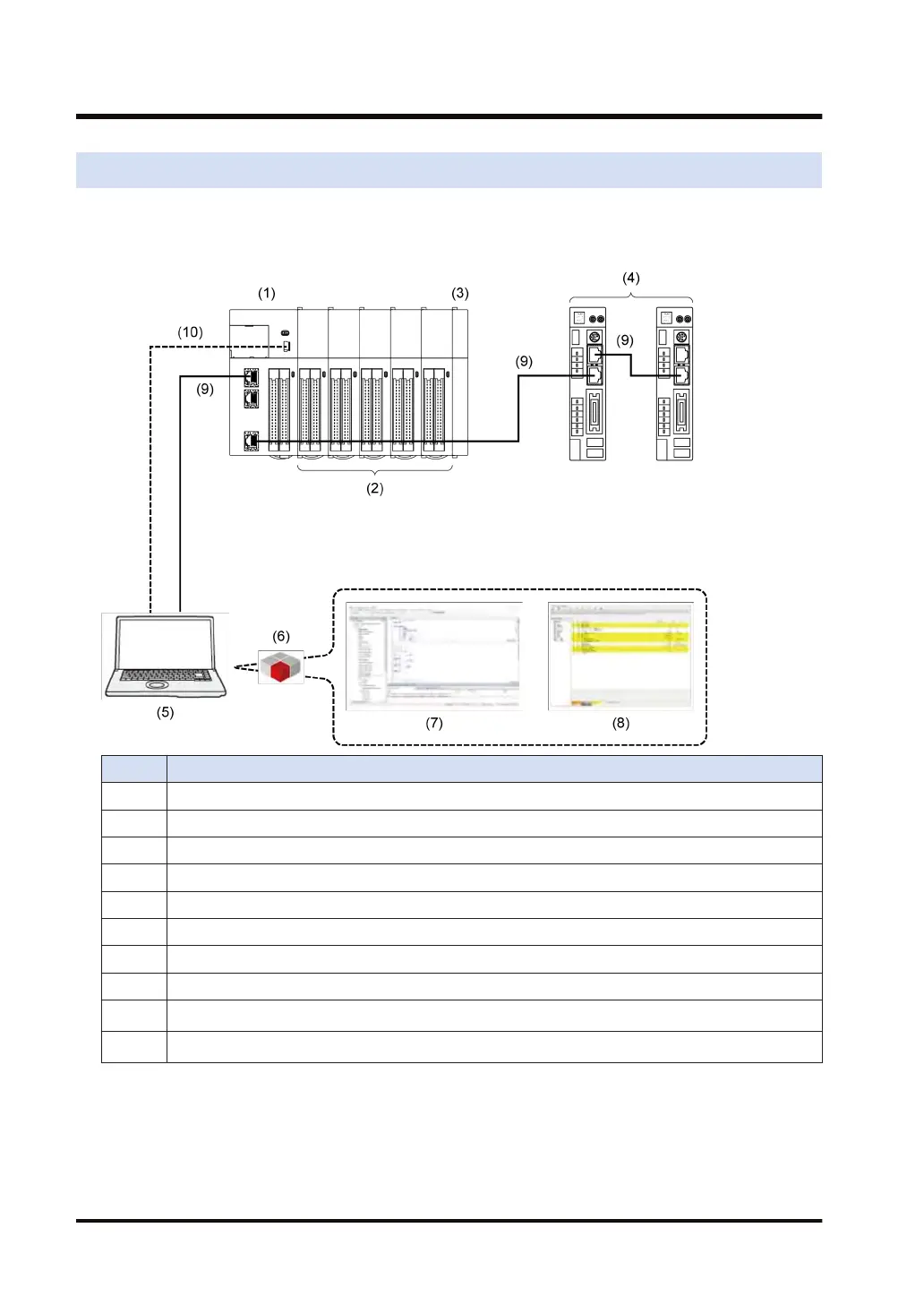
5.1 System Configuration Diagram
The figure below shows the configuration of the GM1 series motion controller (controller and
expansion units), servo amplifiers, and PC. GM Programmer and P
ANATERM Lite for GM
communicate with the GM1 Controller via Gateway.
No. Name
(1) GM1 Controller
(2) Expansion unit
(3) End unit
(4) Servo amplifier
(5) PC (on which GM Programmer and PANATERM Lite for GM are installed)
(6) Gateway, CodeMeter
(7) GM Programmer
(8) PANATERM Lite for GM
(9)
Ethernet cable
(Note 1)
(10)
USB cable
(Note 1)
(Note 1)
Use either Ethernet cables or USB cables.
5.1 System Configuration Diagram
5-2 WUME-GM1ETCSU-01

 Loading...