WWW.100Y.COM.TW WWW.100Y.COM.TW WWW.100Y.COM.TW
WWW.100Y.COM.TW WWW.100Y.COM.TW WWW.100Y.COM.TW
WWW.100Y.COM.TW WWW.100Y.COM.TW WWW.100Y.COM.TW
WWW.100Y.COM.TW WWW.100Y.COM.TW WWW.100Y.COM.TW
WWW.100Y.COM.TW WWW.100Y.COM.TW WWW.100Y.COM.TW
WWW.100Y.COM.TW WWW.100Y.COM.TW WWW.100Y.COM.TW
WWW.100Y.COM.TW WWW.100Y.COM.TW WWW.100Y.COM.TW
WWW.100Y.COM.TW WWW.100Y.COM.TW WWW.100Y.COM.TW
WWW.100Y.COM.TW WWW.100Y.COM.TW WWW.100Y.COM.TW
WWW.100Y.COM.TW WWW.100Y.COM.TW WWW.100Y.COM.TW
WWW.100Y.COM.TW WWW.100Y.COM.TW WWW.100Y.COM.TW
WWW.100Y.COM.TW WWW.100Y.COM.TW WWW.100Y.COM.TW
WWW.100Y.COM.TW WWW.100Y.COM.TW WWW.100Y.COM.TW
WWW.100Y.COM.TW WWW.100Y.COM.TW WWW.100Y.COM.TW
WWW.100Y.COM.TW WWW.100Y.COM.TW WWW.100Y.COM.TW
WWW.100Y.COM.TW WWW.100Y.COM.TW WWW.100Y.COM.TW
WWW.100Y.COM.TW WWW.100Y.COM.TW WWW.100Y.COM.TW
WWW.100Y.COM.TW WWW.100Y.COM.TW WWW.100Y.COM.TW
WWW.100Y.COM.TW WWW.100Y.COM.TW WWW.100Y.COM.TW
WWW.100Y.COM.TW WWW.100Y.COM.TW WWW.100Y.COM.TW
WWW.100Y.COM.TW WWW.100Y.COM.TW WWW.100Y.COM.TW
WWW.100Y.COM.TW WWW.100Y.COM.TW WWW.100Y.COM.TW
WWW.100Y.COM.TW WWW.100Y.COM.TW WWW.100Y.COM.TW
WWW.100Y.COM.TW WWW.100Y.COM.TW WWW.100Y.COM.TW
WWW.100Y.COM.TW WWW.100Y.COM.TW WWW.100Y.COM.TW
WWW.100Y.COM.TW WWW.100Y.COM.TW WWW.100Y.COM.TW
WWW.100Y.COM.TW WWW.100Y.COM.TW WWW.100Y.COM.TW
WWW.100Y.COM.TW WWW.100Y.COM.TW WWW.100Y.COM.TW
WWW.100Y.COM.TW WWW.100Y.COM.TW WWW.100Y.COM.TW
WWW.100Y.COM.TW WWW.100Y.COM.TW WWW.100Y.COM.TW
WWW.100Y.COM.TW WWW.100Y.COM.TW WWW.100Y.COM.TW
WWW.100Y.COM.TW WWW.100Y.COM.TW WWW.100Y.COM.TW
WWW.100Y.COM.TW WWW.100Y.COM.TW WWW.100Y.COM.TW
WWW.100Y.COM.TW WWW.100Y.COM.TW WWW.100Y.COM.TW
WWW.100Y.COM.TW WWW.100Y.COM.TW WWW.100Y.COM.TW
WWW.100Y.COM.TW WWW.100Y.COM.TW WWW.100Y.COM.TW
WWW.100Y.COM.TW WWW.100Y.COM.TW WWW.100Y.COM.TW
WWW.100Y.COM.TW WWW.100Y.COM.TW WWW.100Y.COM.TW
* Please read your User's manual carefully so that you will understand the operation and safety precautions before attempting to operate the system.
C-15
Speed controller Brake Unit Options Index
EX type
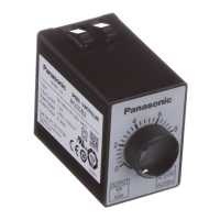
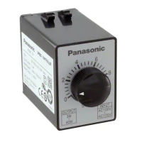
Speed controller
* Please read your User's manual carefully so that you will understand the operation and safety precautions before attempting to operate the system.
C-14
Unidirectional rotation and electric brake
9
<Precautions>
1. When SW2 and SW3 are switched from RUN to
STOP, electric braking is applied for approx. 5
sec, or until the motor stops.
SW2 and SW3 must be operated
simultaneously. Otherwise, abnormal operation
occurs (full speed rotation for a short time),
causing the motor temperature rises
excessively.
2. The number of start/stop cycles must be 6/min.
or less.
3. When using cooling fan motor or motor with
thermal protector, also see page C-20.
4. Insert R1 and C1 to protect relay contact.
5. R2 restricts discharge current in case of
capacitor short circuit during braking.
<Precautions>
1. Connect a fixed resistor (R3) in place of
external speed changer (VR).
• When no external speed changer is required,
the speed can be adjusted from the
maximum speed control.
<Precautions>
1. Power (SW1) should be turned on at least 0.5
sec before turning on of the start signal (SW6).
2. When the motor is not operated for a
prolonged time, turn off power switch (SW1).
<Precautions>
1. Connect a fixed resistor (R3) in place of
external speed changer (VR).
• When no external speed changer is required,
the speed can be adjusted from the maximum
speed control.
• With the external speed changer connected,
the motor can be started/stopped with a small
signal through SW6 contact while the power
switch SW1 (see diagram above) is on. The
SW6 provides shorter start-up time than SW1.
Start/stop control with small signal Operation from maximum speed control Operation from maximum speed control
<Precautions>
1. To change rotating direction of induction motor:
Provide a motor halt period. Switch over SW2 after complete stop of the motor.
2. To change rotating direction of reversible motor:
A motor halt period is not necessary. Switch over SW2 while keeping SW1 turned ON. When configuring
SW2 with relay contacts, use a relay having large gap between contacts (e.g. HG/HP relay from
Matsushita Electric Works, Ltd.) to prevent malfunction due to short-circuited capacitor.
3. For motors for cooling fan and motors with thermal protector, also refer to page C-20.
4. When using independent relay contacts for SW2 to change over normal/reverse, interlock both contacts so
that they will not close simultaneously.
5. The spark killer consisting of R1 and C1 must be used to protect the relay contacts.
SW1 : Power switch
SW2 : RUN/STOP switch
SW3 : Brake start switch
Run
Stop
STOP
SW2
SW3
SW1
3
6
4
5
Pin No.
R3 20 kΩ 1/4 W
To TG
STOP
RUN
SW3
Run
RUNRUN
ON
Braking
Braking
Speed change only
8
SW1 : Power switch
SW2 : Normal/reverse selector switch
Normal Reverse
RUN RUN
SW1
SW2
CW
CCW
2
1
8
7
3
6
5
4
Pin No.
Capacitor
Pink
Pink
TG
Gray
Black
White
Motor
Rated voltage
input
CW
VR
2
1
3
2
1
8
7
3
6
5
4
Pin No.
Capacitor
Pink
Pink
TG
Black
Motor
Rated voltage
input
VR
2
1
3
Gray
White
SW2
C1
CCW
CW
R1
C1R1
3
6
5
4
Pin No.
VR
2
3
1
RUN
SW6
DC10V 10mA
STOP
STOP
3
6
5
4
Pin No.
R3 20 kΩ 1/4 W
To TG
To TG
Stop
SW1
Run
ON
External speed changer
(DVOP002)
1/4 W, 20 kW, taper B
2
1
8
7
3
6
5
4
Pin No.
Capacitor
Pink
Pink
TG
Gray
Black
White
Motor
Rated voltage
input
CW
VR
2
1
STOP
STOP
RUN
RUN
SW3
SW2
R2
C1
R1
2
1
7
8
3
6
5
4
Pin No.
Capacitor
Pink
Pink
TG
Gray
Black
White
Motor
Rated voltage
input
CW
VR
2
3
1
3
STOP
STOP
RUN
RUN
SW3
SW2
R2
R1
C1
Speed controller
Speed controller
Speed controller
Speed controller
Unidirectional rotation Normal/reverse rotation
SW1
SW2
R1+C1 DV0P008 (option)
100 V supply system 5 A or more at 125 VAC
200 V supply system 5 A or more at 250 VAC
This wiring diagram causes the motor to rotate clockwise
when viewed from the motor shaft end.
To run the motor counterclockwise, interchange the
connecting point of black and gray leads.
25 W or smaller
40 W or larger
• Connection according to this wiring
diagram causes the motor to rotate
clockwise when viewed from the
motor shaft end. To run the motor
counterclockwise, interchange the
connecting point of black and gray
leads.
SW1
SW2
SW3 DC10 V 10 mA
R1+C1 DV0P008 (option)
R2 DV0P003 (option)
100 V supply system 5 A or more at 125 VAC
200 V supply system 5 A or more at 250 VAC
SW1
NFB
SW1
NFB
SW1
NFB
SW1
NFB
 Loading...