Do you have a question about the Panasonic NN-GD356W and is the answer not in the manual?
Illustrates electrical connections and wire colors for oven components.
Explains how microwave power levels are adjusted using PWM signals.
Details the function of the high-voltage inverter circuit in supplying power to the magnetron.
Describes the operation sequence for specific cooking modes like defrost and auto menus.
Emphasizes the importance of proper grounding for safety during operation and repair.
Highlights dangers associated with the high-voltage inverter, including hot components and stored charge.
General precautions to take before replacing any component in the oven.
Instructions for replacing a blown fuse and related interlock switches.
Warning against inserting foreign objects into the oven cavity during operation.
Steps to ensure the oven is properly reassembled and safe after repair.
Caution regarding sharp edges on the unit during handling and installation.
Step-by-step guide for removing and replacing the magnetron component.
Instructions for disassembling and replacing the main control board and user interface.
Procedure for replacing the low voltage transformer and power relays.
Steps for removing and replacing the cooling fan motor.
Detailed instructions for disassembling and reassembling the oven door.
Guide for removing and replacing the turntable drive motor.
Procedure for disconnecting and removing the quartz heating element.
Steps for safely removing and replacing the high-voltage inverter unit.
Tests for door interlock switches and power relay continuity.
Procedure for testing the short switch continuity.
Method for checking magnetron filament continuity and case shorts.
Describes checking continuity of the membrane key board's switch terminals.
Testing procedures for the high-voltage inverter power supply unit.
Explains how to test the temperature thermistor by measuring its resistance.
Guidance on mounting and adjusting door latch switches and ensuring proper door closure.
Method for measuring the oven's microwave output power using a simple test.
Lists symptoms, causes, and corrections for oven stopping during cooking.
Troubleshooting steps for issues with the digital control circuit and display.
Diagnosing problems related to the high-voltage inverter and magnetron using failure codes.
A simplified method for identifying issues between the inverter and magnetron.
Guide on testing various semiconductor components like diodes, transistors, and IGBTs.
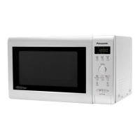
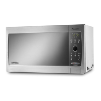
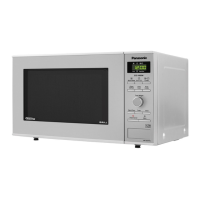
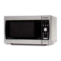
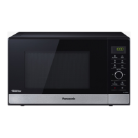
Visual representation of the oven's components and their assembly.
Comprehensive list of all part numbers and descriptions for ordering.
Detailed breakdown of the oven door components and their arrangement.
Lists various wiring harnesses and lead wires used in the oven.
Details the assembly of the front panel and control interface base.
Lists parts specific to the NN-GD376S model's escutcheon base assembly.
Lists parts for NN-GD366M/GD356W models' escutcheon base assembly.
Information regarding the packaging of the unit and included accessories.
Specific list of main components within the high-voltage inverter unit.
Detailed schematic diagram of the digital programmer circuit for the NN-GD376S model.
Detailed schematic diagram of the digital programmer circuit for NN-GD366M/GD356W models.
A detailed list of components used within the digital programmer circuit.
| Capacity | 23 L |
|---|---|
| Microwave Power | 800 W |
| Grill Power | 1000 W |
| Weight | 13.5 kg |
| Grill | Yes |
| Convection | No |
| Auto Cook Menu | Yes |
| Defrost Function | Yes |
| Child Lock | Yes |
| Color | White |
| Turntable Diameter | 27 cm |