Do you have a question about the Panasonic NN-GF560M and is the answer not in the manual?
Controls output power by signal from Digital Programmer Circuit (DPC) using PWM.
Supplies 4,000V DC to magnetron tube, replacing HV transformer, capacitor, diode.
Digital programmer circuit determines power level and cooking time for auto modes.
Ensure appliance is properly grounded before beginning repair work.
High voltage and temperature warnings for Inverter Power Supply (U) and heat sink.
Always unplug power cord and discharge capacitors before part replacement.
Check screws, connections, and test for microwave leakage after repair.
Procedure to remove and replace the HV Inverter power supply unit.
Steps to remove and replace the magnetron, including safety precautions.
Procedure for disassembling and replacing the DPC board and membrane switch.
Steps to remove and replace low voltage transformer and power relays.
Procedure to remove and re-install the oven door assembly.
Tests continuity of latch switches and power relay RY1.
Checks magnetron filament continuity and resistance to case.
Tests inverter power supply operation and input current under specific conditions.
Measures microwave output by checking water temperature rise after 1 minute.
Identifies causes and corrections for oven stopping during cooking.
Lists symptoms, causes, and corrections for various oven malfunctions.
Guides troubleshooting for inverter circuit and magnetron using failure codes.
Troubleshooting guide for issues related to the Digital Programmer Circuit.
Diagram showing the assembly of all oven components.
Detailed list of all replacement parts with part numbers.
List of parts related to the escutcheon base assembly.
List of parts comprising the oven door assembly.
Schematic diagram of the Digital Programmer Circuit.
List of parts related to the Digital Programmer Circuit.
| Brand | Panasonic |
|---|---|
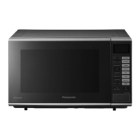
| Model | NN-GF560M |
| Category | Microwave Oven |
| Language | English |