7-6. Timing chart from Mode SW to System control IC
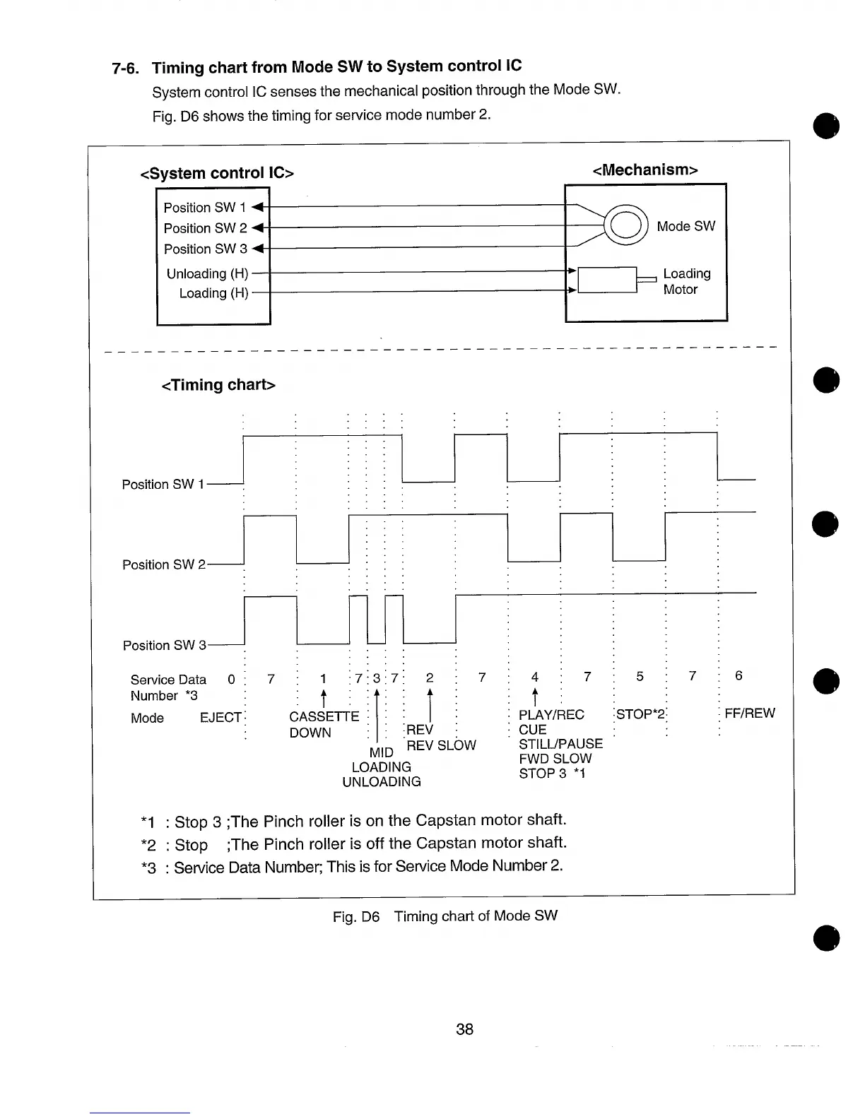
System control IC senses the mechanical position through the Mode SW.
Fig. D6 shows the timing for service mode number 2.
<System control IC>
<Mechanism>
Position SW 1 +
Position SW 2 +
~
Mode SW
Position SW 3 +
Unloading (H)
Loading (H)
:D h;%:’
——.—.———
_—_——————————————
———————
———————
——.———
——————
<Timing chart>
. . . .
. . .
. . . .
. . .
. . .
.,.
Position SW 1 : :::.
.:::
. . . .
. . . .
. . . .
. . .
. . .
Position SW 2 ~
.;:: :
;
. .
. . .
. . . .
Position SW 3
.-. .
.~i:;:
. . .
. . . .
Service Data
o ; 7 : 1 :7:3:7: 2 : 7 : 4 : 7 I 5 ~ 7
:6
Number *3 :
t ~
It
t ~ ~ ~
Mode
EJECT [
CASSETTE : ; : ;
: p~Y/REC ;STOP*2;
; FF/REW
DOWN : :
:REV ; ; CUE
MID REV SLOW
STILUPAUSE
LOADING
FWD SLOW
UNLOADING
STOP 3 *1
*1 : Stop 3 ;The Pinch roller is on the Capstan motor shaft.
*2 : Stop ;The Pinch roller is off the Capstan motor shaft.
*3 : ServiceData Number;This isfor ServiceMode Number 2.
Fig. D6 Timing chart of Mode SW
38