8. SYSTEMCONTROL CIRCUIT& MECHANISMCONTROL CIRCUIT
➤
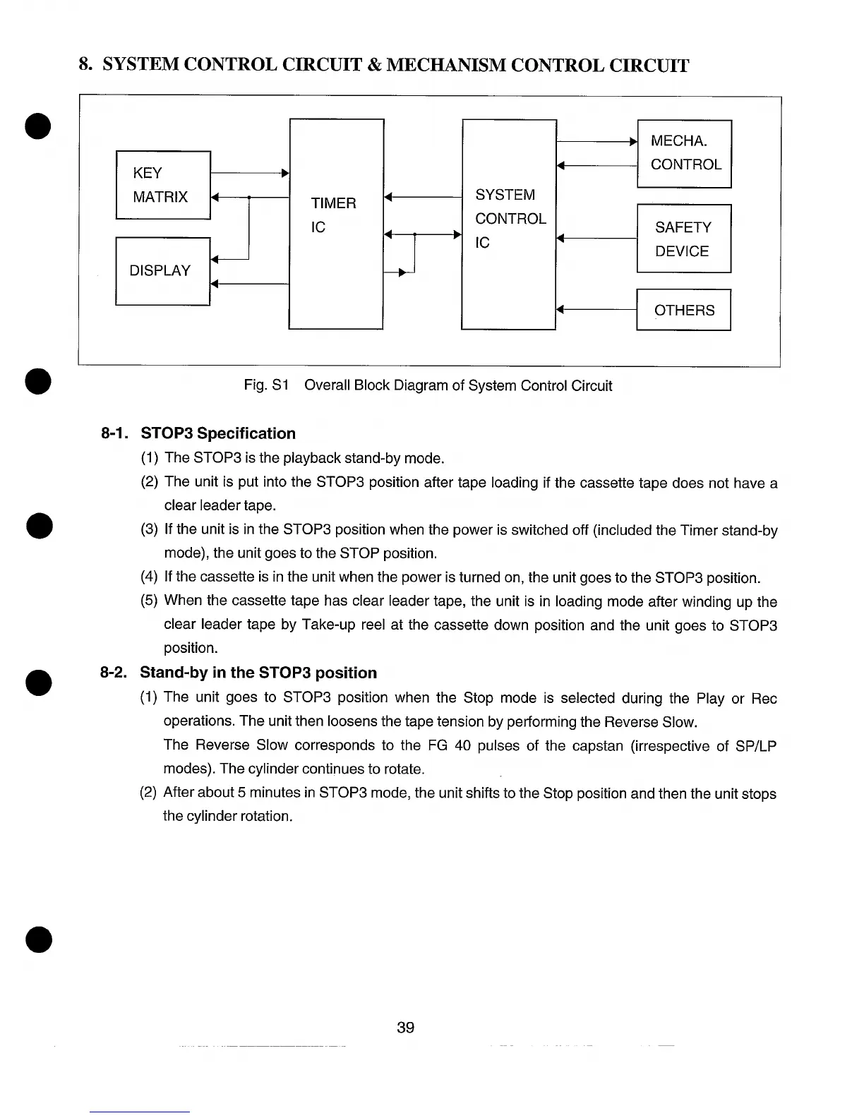
MECHA.
KEY
➤
4
CONTROL
MATRIX
4
TIMER
4
SYSTEM
Ic
CONTROL
4
➤
SAFETY
Ic
4
DEVICE
DISPLAY
4
4
OTHERS
Fig. S1 Overall Block Diagram of System Control Circuit
8-1. STOP3 Specification
(1)
(2)
(3)
(4)
(5)
The STOP3 is the playback stand-by mode.
The unit is put into the STOP3 position after tape loading if the cassette tape does not have a
clear leader tape.
If the unit is in the STOP3 position when the power is switched off (included the Timer stand-by
mode), the unit goes to the STOP position.
If the cassette is in the unit when the power is turned on, the unit goes to the STOP3 position.
When the cassette tape has clear leader tape, the unit is in loading mode after winding up the
clear leader tape by Take-up reel at the cassette down position and the unit goes to STOP3
position.
8-2. Stand-by in the STOP3 position
(1)
(2)
The unit goes to STOP3 position when the Stop mode is selected during the Play or Rec
operations. The unit then loosens the tape tension by performing the Reverse Slow.
The Reverse Slow corresponds to the FG 40 pulses of the capstan (irrespective of SP/LP
modes). The cylinder continues to rotate.
After about 5 minutes in STOP3 mode, the unit shifts to the Stop position and then the unit stops
the cylinder rotation.
39