READ CAREFULLY BEFORE ATTEMPTING ALIGNMENT
1. Set power source voltage to 230/240 V AC.
2. Set volume control to maximum.
3. Set band switch to AM, FM or LW.
4. Output of signal generator should be no higher than necessary to obtain an output reading.
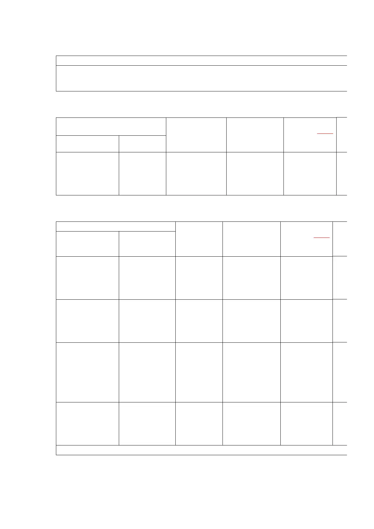
- AM-IF ALIGNMENT
Signal Generator or Sweep
Generator
Radio Dial Setting Indicator
(Electronic
Voltmeter or
oscilloscope)
Adjustment
(Shown in Fig. 1
)
Connections Frequency
Fashion a loop of
several turns of
wire and radiate
signal into loop of
receiver.
459 kHz 30%
Mod. at 400 Hz
Point of non-
interference. (on/
about 600 kHz)
Connect vert.
amp. of scope to
test point TP4.
Negative side to
test point TP5.
T2 (AM IFT)
- AM-RF ALIGNMENT
Signal Generator or Sweep Generator Radio Dial
Setting
Indicator
(Electronic
Voltmeter or
oscilloscope)
Adjustment
(Shown in Fig. 1
)
Connections Frequency
Fashion a loop of
several turns of
wire and radiate
signal into loop of
receiver.
511 kHz Variable
capacitor fully
closed.
Connect vert.
amp. of scope to
test point TP4.
Negative side to
test point TP5.
L7 (AM OSC
Coil)
Fashion a loop of
several turns of
wire and radiate
signal into loop of
receiver.
1650 kHz Variable
capacitor fully
opened.
Connect vert.
amp. of scope to
test point TP4.
Negative side to
test point TP5.
CT3 (AM OSC
Trimmer)
Fashion a loop of
several turns of
wire and radiate
signal into loop of
receiver.
600 kHz Tune to signal Connect vert.
amp. of scope to
test point TP4.
Negative side to
test point TP5.
[*1] L3 (AM ANT
Coil)
by
Fashion a loop of
several turns of
wire and radiate
signal into loop of
receiver.
1500 kHz Tune to signal Connect vert.
amp. of scope to
test point TP4.
Negative side to
test point TP5.
CT4 (AM ANT
Trimmer)
[*1] Fix antenna coil with wax after completing alignment
10

 Loading...