
Do you have a question about the Panasonic RM-1100 and is the answer not in the manual?
| Brand | Panasonic |
|---|---|
| Model | RM-1100 |
| Category | Car Receiver |
| Language | English |
Covers technical details of the FM/AM stereo cassette deck tuner amplifier.
Crucial safety advice for servicing the unit.
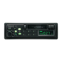
Identifies and describes all controls on the front panel of the unit.
Provides steps and diagrams for taking the unit apart.
Shows the placement of electrical components on internal boards.
Details component removal steps and the hardware involved.
Illustrates the internal wiring connections of the unit.
Shows output signal timing and waveform characteristics.
Details the steps for aligning various sections of the tuner and deck.
Identifies specific test points for alignment procedures.
Details alignment steps for FM RF and DC balance sections.
Details alignment steps for FM stereo and azimuth.
Provides diagrams showing test points for alignment.
Explains LCD connections, signal timing, and waveforms.
Details the function of each terminal on the LCD driver.
Shows the physical layout, block diagram, and connections of IC7.
Details the function of each terminal on IC7.
Illustrates how the unit connects within an audio system.
Provides functional block diagrams for key integrated circuits.
Presents the overall schematic of the main circuit board.
Shows the location of integrated circuits on the main schematic.
Provides in-depth schematic diagrams of the main circuitry.
Shows the placement of components on the main circuit board.
Illustrates common electronic component symbols used in diagrams.
Shows the schematic and component layout for the AM section.
Shows the schematic and component layout for the LCD driver.
Provides the schematic and component layout for the tape deck.
Provides the schematic and component layout for the power supply.
Shows component placement on the tape deck circuit board.
Shows component placement on the power source circuit board.
Shows the schematic and component layout for tape EQ/ambience.
Illustrates the wiring between different circuit boards.
Shows how various internal circuit boards are interconnected.
Depicts the overall functional flow and interaction of unit components.
Shows the location and identification of mechanical parts.
Shows the location of cabinet and exterior parts.
Shows the location of various electrical components on PCBs.
Continues showing component locations on different circuit boards.
Lists all replaceable mechanical parts with their codes and descriptions.
Lists part numbers for integrated circuits, transistors, and diodes.
Lists part numbers for coils, transformers, and variable components.
Lists part numbers for switches and cabinet/exterior parts.
Lists all resistors with their part numbers and resistance values.
Lists capacitor part numbers and their capacitance values.
Lists additional capacitor part numbers and their values.
Lists final capacitor part numbers and their values.
Covers rated power, impedance, power source, consumption, dimensions, weight.
Outlines the process and hardware for disassembling the power amplifier.
Shows the placement of components on the power amplifier circuit boards.
Provides the schematic diagram for the power amplifier unit.
Shows the circuit board layout and wiring connections for the power amplifier.
Lists all replaceable components for the power amplifier unit.
Details power source, consumption, gain, control, dimensions, and weight.
Identifies controls and connections on the auto volume unit.
Outlines the process and hardware for disassembling the unit.
Provides schematics for both one and two FET configurations of the unit.
Shows circuit board layouts and wiring for the auto volume unit.
Details the steps for performing gain alignment on the unit.
Lists all replaceable components for the auto volume unit.
Details the parts included in the radio cassette accessory.
Details the parts included in the power amplifier accessory.
Details the parts included in the auto volume accessory.
Details the parts included in the head set accessory.
Details the parts included in the junction box accessory.






 Loading...