EasyManua.ls Logo

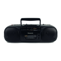
Panasonic RX-S35 - Measurements and Adjustments; Alignment Instructions Overview; AM Band Alignment Procedures; FM Band Alignment Procedures

Panasonic RX-S35
12 pages
To Next Page IconTo Next Page
To Previous Page IconTo Previous Page
Loading...
F.
When
the
tape
is
tangled
around
the
pinch
roller.
if
\—
a
il
SO
“7
:
om
ep
eo
|
|
Sw
(G)
Fig.
9
1.
Remove
two
screws.
(1.74)
(Fig.
10)
1.
Push
the
cabinet
catch
in
the
|
direction
of
the
arrow,
and
remove
the
printed
circuit
board.
(Fig.
9)
2.
Remove
three
screws-G.
H.
How
to
replace
the
tuning
knob.
(1.6x3.5)
(Fig.
9)
:
|
G.
Operational
check
procedures
for
the
mechanism.
| |
INO
Chassis
Fig.
13
Middle
Gear
1.
Remove
two
screws.
(1.73)
(Fig.
12)
2.
Insert
the
plug
into
the
socket.
Note:
Set
S6
to
on
during
fowerd.
Insert
the
tuning
knob
into
the
dial
chassis.
BLOCK
DIAGRAM
¢RADIO>
a
-
IC
|
=
fei
IC
2
|
FM
)
HEAD
FM
Ist|
|
10.7
|
|
SEE
4
err
(1)
FRONT(6)
MHz
HAD
FM/AM
IF
|
_
END
AMP
&
DET
LB
Qt
ss
AM
«osc
|
_|AM_ANTI|
AM
RF
L(])
/MIX
core
Fy]
AMP
-
<PLAYBACK>(Lch)
>
|
|
|
|
164
1C§
;
IC
6
Lch
4.
§
@
ee
|
Rev
:
|
|
|
Lch
(>
(2)
|
Fwd
“SY
¢
(s
VR4
o
PLAYBACK
|
x
HEAD.
(}
(6)
eo
Rev
Rech
ow
©
Fwd
CP
Q2
03
NS
SWIT-
“'
{CHING
SWITCHING
:
(10)
ARCh)
|
Fig.
11
2.
Remove
the
spring.
Remove
the
cassette
tape
by
moving
it
left
and
right,
and
also
remove
the
cassette
lid.
(Fig.
11)
l.
Take
care.
perly.
IC3
mee
a
On"
U7
JAM
OSC
ee
:
COIL
VAN
48
:
|
WY
D1
FM
ST
IND
J2
|
AV
HEADPHONE
(Leh)
[
3s0qQ
Fig.
14
Install
so
that
the
minus
(-)
terminal
of
the
battery
and
the
ground
ter-
minal
of
the
circuit
board
touch
pro-
@
ALIGNMENT
INSTRUCTION
ee
cstgelsgs
mete
Taga
BRL
it
an
SIGNAL
GENERATOR
or
|
Banp
SWEEP
GENERATOR
Fed
ee
gt
__-:
MEASUREMENTS
AND
ADJUSTMENTS
READ
CAREFULLY
BEFORE
ATTEMPTING
ALIGNMENT
5.
Set
power
source
voltage
to
3V
DC.
6.
Output
of
signal
generator
should
be
no
higher
than
necessary
to
obtain
an
output
reading.
1.
Set
volume
control
to
maximum.
.
2.
Set
band
switch
to
AM
or
FM
ST.
|
3.
Set
balance
control
to
center.
4.
Set
function
selector
to
radio.
@
AM
ALIGNMENT
a
-
een
wi
eee
|
RADIO
DIAL
(ELECTRONICS
-
WEEP
GENERA
|
CONNECTIONS
|FREQUENCY|
~
|
or
SCOPE)
AM-IF
ALIGNMENT
|
Fashion
loop
of
Output
meter
several
turns
of
455
kHz
Point
of
non-
j
|
:
(1)
‘wire
and
radiate
30%
Mod.
|
interference.
(on/
|
across
voice
T3
(AM
IFT)
ae
for
maximum
signal
into
loop
of
|
at
400Hz
|
about
600kHz)
coil.
a
receiver.
AM-RF
ALIGNMENT
|
|
|
Tuning
capacitor
L4(AMOSC
__
|
Adjust
for
maximum
Tuning
capacitor
CT4
(AM
OSC
|
Adjust
for
maximum
AM
550kHz
|
Tune
to
signal.
output.
Adjust
L3
by
moving
coil
bobbin
(*
1)
Cement
antenna
bobbin
with
wax
after
completing
alignment.
along
ferrite
core.
@
FM
ALIGNMENT
(#1)
L3
(AM.
ANT
Coil)
Adjust
for
maximum
output.
Repeat
steps
(2)~(5).
CT3
(AM
ANT
1,500
kHz
Trimmer)
INDICATOR
(ELECTRONICS
VOLTMETER
or
SCOPE)
RADIO
DIAL
SETTING
REMARKS
ADJUSTMENT
‘CONNECTIONS
|FREQUENCY
High
side
thru.
0.001yuF
to
test
point
8
.
Negative
side
to
test
point
Connect
vert.
amp.
of
scope
to
test
point
;
Negative
side
to
test
point
Earth.
*
2)
Adjust
for
maxi-
FM-RF
ALIGNMENT
Coil)
| |
mum
output.
|
Variable
-
Output
meter
|
Capacitor
©
across
|
|
Variable
ee
109.2MHz
|
capacitor
CT2
re
ane
|
7
|
fully
open.
fully
closed.
voice
coil.
|
90MHz
Tune
to
signal.
Li
(FM
a
Soin
(*
2)
Adjust
for
maxi-
Trimmer)
|
Repeat
steps
nt;
proper
tuning
is
the
center
frequency.
Adjust
for
maximum
amplitude.
|
(Refer
to
fig.
18.)
Point
of
non-
interference.
(on/
about
90
MHz)
10.7MHz
Adjust
for
maximum
amplitude.
(Refer
to
fig.
19.)
Connect
to
test.
point
W
through
FM
dummy
>
antenna.
Negative
side
to
test
point
106
MHz.
oo
(3)~(6).
_(*2)
Three
output
responses
will
be
prese
4
V
Be
sure
to
fold
at
the
(W)
mark
so
that
mark
is
on
the
outside.

Related product manuals