© Panasonic HA Air-Conditioning (M) Sdn. Bhd. 2010.
Unauthorized copying and distribution is a violation of law.
Order No: RAC1009001C8
Model No.
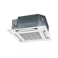
Indoor Unit
(KA1E5 Series)
S-22KA1E5S
S-28KA1E5S
S-36KA1E5S
S-45KA1E5S
S-22KA1E5
S-28KA1E5
S-36KA1E5
S-45KA1E5
S-56KA1E5
S-63KA1E5
S-71KA1E5
(YA1E5 Series)
S-22YA1E5
S-28YA1E5
S-36YA1E5
S-45YA1E5
S-56YA1E5
(UA1E5 Series)
S-63UA1E5
S-71UA1E5
S-90UA1E5
S-100UA1E5
S-125UA1E5
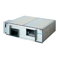
(NA1E5 Series)
S-22NA1E5
S-28NA1E5
S-32NA1E5
S-36NA1E5
S-40NA1E5
S-45NA1E5
S-56NA1E5
(MA1E5 Series)
S-45MA1E5
S-56MA1E5
S-63MA1E5
S-71MA1E5
S-90MA1E5
S-100MA1E5
S-125MA1E5
Outdoor Unit
U-8EA1E8 U-10EA1E8
PRECAUTION OF LOW TEMPERATURE
In order to avoid frostbite, be assured of no refrigerant leakage during the installation or repairing of refrigerant circuit.
WARNING
This service information is designed for experienced repair technicians only and is not designed for use by the general public.
It does not contain warnings or cautions to advise non-technical individuals of potential dangers in attempting to service a product.
Products powered by electricity should be serviced or repaired only by experienced professional technicians. Any attempt to
service or repair the products dealt with in this service information by anyone else could result in serious injury or death.