17
■
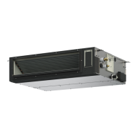
Low Silhouette Ducted Type (F1 Type)
3-11. Required Minimum Space for Installation and
Service
● This air conditioner is usually installed above the ceiling so
that the indoor unit and ducts are not visible. Only the air
intake and air outlet ports are visible from the unit bottom.
● The minimum space for installation and service is shown in
Fig. 3-35 and Table 3-1.
Type 22, 28, 36, 45, 56 73, 90 106, 140, 160
A (Length) 780 1,080 1,560
● It is recommended that space be provided (450 × 450 mm)
for checking and servicing the electrical system.
● The detailed dimensions of the indoor unit is shown in Fig.
3-36 and Table 3-2.
262
100
58025
H HI
27
GBG
K40
C
75
(
150
)
115
186
65
90
100
43
43
185
186
310
262
3131
35
70 130
175
630 3125
190
285
160
25 30
E- 3.1
F- 3.3
1
2
3
4
9
10
11
6
5
7
8
12
13
580
A (Suspension bolt pitch)
min.250
Electrical
component box
Inspection
access
450 × 450
Refrigerant
tubing
min.650
Indoor unit
min.400
min.250
Unit: mm
Fig. 3-35
Table 3-1
Unit: mm
Dimension
Type
ABCD
No. of holes
GH I GK
EF
22, 28, 36, 45, 56 646
500
(100 × 5)
700 780 18 12 73 96
300
(100 × 3)
492 161
73, 90 946
900
(100 × 9)
1,000 1,080 26 20 23 41
700
(100 × 7)
782 171
106, 140, 160 1,426
1,300
(100 × 13)
1,480 1,560 26 28 63 81
1,100
(100 × 11)
1,262 182
Table 3-2
Unit: mm
1
Refrigerant tubing joint (liquid tube)
2
Refrigerant tubing joint (gas tube)
3
Upper drain port VP25 (O.D. 32 mm)
200 flexible hose supplied
4
Bottom drain port VP25 (O.D. 32 mm)
5
Suspension lug (4 – 12 × 37 mm)
6
Power supply outlet (2 – ø30 mm)
7
Fresh air intake port (ø150 mm)
8
Flange for flexible air outlet duct
9
Tube cover
0
Electrical component box
!
Wind pressure endurance
@
Flange for air intake duct
#
Filter
Intake port side
A (Flange O.D.)
Inspection access
(450×450)
(Field supply)
(Hole)
(Hole)
Inspection access panel
Ceiling
J (Flange O.D.)
D (Suspension bolt pitch)
Outlet duct side
(Flange O.D.)
Unit: mm
Fig. 3-36
100p×2=200
(Suspension bolt pitch)
Power, inter-unit wiring
Panaindoor336013Eng.indb17Panaindoor336013Eng.indb17 2012/03/2121:07:072012/03/2121:07:07
 Loading...