24
3-20. Installing the Duct
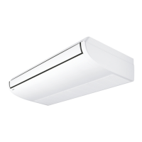
Connect the duct supplied in the field as shown in Fig. 3-58.
Fig. 3-58
Air inlet side
• Attach the duct and intake-side fl ange (fi eld supply).
• Connect the fl ange to the main unit with 10 - ø3.1 (Hole)
screws.
•
Wrap the intake-side fl ange and duct connection area with
aluminum tape or something similar to prevent air escaping.
CAUTION
When attaching a duct to the intake-side, be sure to attach
an air filter inside the air passage on the intake-side. (Use
an air filter whose dust collecting efficiency is at least 50%
in a gravimetric technique.)
The included filter is not used when the intake duct is
attached.
Air outlet side
• Connect the duct according to the air outside of the
outlet-side fl ange.
• Wrap the outlet-side fl ange and the duct connection
area with aluminum tape or something similar to
prevent air escaping.
CAUTION
●
Be sure to insulate the duct to prevent condensation from
forming. (Material: glass wool or polyethylene foam, 25 mm thick)
●
Use electric insulation between the duct and the wall when
using metal ducts to pass metal laths of the net or fence
shape or metal plating into wooden buildings.
●
Be sure to explain about the way of maintaining and cleaning
local procurements (air filter, grille [both air outlet and suction
grille], etc.) to your customer.
3-21. Suspending the Indoor Unit
Depending on the ceiling type:
•
Insert suspension bolts as shown in the diagram. (Fig. 3-59)
or
• Use existing ceiling supports or construct a suitable
support as shown in the diagram. (Fig. 3-60)
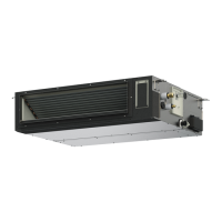
Fig. 3-59
Fig. 3-60
WARNING
It is important that you use extreme care in supporting
the indoor unit inside the ceiling. Ensure that the ceiling
is strong enough to support the weight of the unit. Before
hanging the unit, test the strength of each attached
suspension bolt.
(1) When placing the unit inside the ceiling, determine the pitch
of the suspension bolts referring to the dimensional data as
shown in Fig. 3-54.
Tubing must be laid and connected inside the ceiling when
suspending the unit. If the ceiling is already constructed,
lay the tubing into position for connection to the unit before
placing the unit inside the ceiling.
(2) Screw in the suspension bolts allowing them to protrude
from the ceiling as shown in Fig. 3-59. (Cut the ceiling
material, if necessary.)
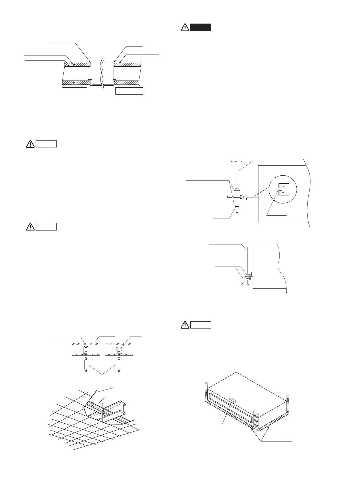
(3) Thread the 3 hexagonal nuts and 2 washers (field supply)
onto each of the 4 suspension bolts as shown in Fig. 3-61
and 3-62. Use 1 nut and 1 washer for the upper part, and 2
nuts and 1 washer for the lower part, so that the unit will not
fall off the suspension lugs.
Fig. 3-61
Fig. 3-62
(4) Adjust the height of the unit.
(5) Check the unit is horizontally level.
CAUTION
●
Make sure the unit is installed level using a level or a vinyl
hose filled with water. In using a vinyl hose instead of a
level, adjust the top surface of the unit to the surface of
the water at both ends of the vinyl hose and adjust the unit
horizontally. (One thing to watch out for in particular is if the
unit is installed so that the slope is not in the direction of the
drain piping, this might cause leaking.) (Fig. 3-63)
Fig. 3-63
(6) Tighten the upper nut.
Hole-in-anchor
Hole-in-plug
Concrete Insert
Suspension bolt (M10 or 3/8")
(field supply)
Ceiling tiles
Ceiling support
Nuts and washers
(use for upper and lower)
Suspension bolt
Suspension lug
Notch
Double nuts
Suspension bolt
Hexagonal nut
Double nuts
Flange
(Field supply)
Connection screw (x10)
Rectangular solid duct
(Field supply)
Main unit
Flange
Insulation material
(Field supply)
Air inlet side
Air outlet side
Level
Vinyl hose
Panaindoor336013Eng.indb24Panaindoor336013Eng.indb24 2012/03/2121:07:102012/03/2121:07:10
 Loading...