Do you have a question about the Panasonic SA-AK28 and is the answer not in the manual?
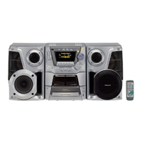
| Type | Mini Hi-Fi System |
|---|---|
| CD Player | Yes |
| Radio Tuner | FM/AM |
| Bluetooth | No |
| USB Port | No |
| Number of Channels | 2 |
| Tape Deck | Yes |
| Speaker Configuration | 2-Way Speakers |
| Playable Media | CD, CD-R |
Details of the amplifier's power output, input sensitivity, and impedance.
Specifications for the FM tuner, including frequency range, sensitivity, and antenna terminal.
Specifications for the AM tuner, including frequency range and sensitivity.
Details on track system and heads for the cassette deck.
Specifications for the CD section, including sampling frequency, decoding, and D/A converter.
Warning about service only by experienced technicians to avoid injury or death.
Lists accessories like remote control, antennas, and AC power cords.
Precautions for handling the traverse deck, focusing on static electricity and laser diode.
Steps for grounding the body and work table to prevent electrostatic discharge.
Cautionary note on removing solder from a short point before connecting the traverse deck.
Caution about procedures other than specified resulting in hazardous radiation exposure.
Shows and explains the Class 1 Laser Product caution labels.
Step-by-step instructions for replacing the fuse in the AC mains plug.
Important information regarding the color coding of wires in the mains lead for correct connection.
Identifies and describes the function of each control on the main unit's front panel.
Lists and describes the buttons located on the center console.
Information on a special gear tool used for manual operation checks and servicing.
Warning regarding sharp edges on chassis components during disassembly and servicing.
Overview of checks for Main, Panel, and Deck Printed Circuit Boards.
Detailed steps for replacing the traverse deck unit.
Instructions on how to replace the traverse unit itself.
Explains the self-diagnostic display function and error code reporting.
Step-by-step guide on how to access the self-diagnostic mode.
Procedure for testing the cassette mechanism and identifying specific error codes.
Procedure for testing the CD mechanism and identifying specific error codes.
Lists error codes and their corresponding problem conditions for the cassette mechanism.
Lists error codes and their corresponding problem conditions for the CD/Changer block.
Lists error codes and their corresponding problem conditions for power supply issues.
Step-by-step instructions for setting up the CD test mode.
Explains how the results of automatic adjustment are indicated in CD test mode.
Procedures for measurements and adjustments related to the cassette deck section.
Detailed procedure for adjusting the head azimuth on the cassette deck.
Steps for performing AM-IF alignment on the tuner.
Identifies alignment points on the cassette deck section.
Identifies alignment points on the tuner section.
Lists terminal functions for the AN8839NSBE2 servo amplifier IC.
Lists terminal functions for the MN662790RSC IC.
Highlights special components important for safety and replacement parts.
Caution regarding static electricity sensitivity of ICs, LSIs, and VLSI.
Schematic of the motor control circuit, including Ta7291P driver.
Schematic of the CD detect circuit.
Schematic of the spindle position circuit.
Component layout for the CD Servo PCB.
Component layout for the Main PCB.
Component layout for the Tuner Pack PCB.
Component layout for the Panel PCB.
Component layout for the Deck 1 Mechanism PCB.
Component layout for the Deck 2 Mechanism PCB.
Component layout for the Motor PCB.
Component layout for the Spindle Position PCB.
Component layout for the CD Detect PCB.
Component layout for the Tuner Pack PCB.
Component layout for the Deck PCB.
Component layout for the Power PCB.
General notes on safety, component identification, and part availability.
Safety warning regarding laser unit handling and replacement.
Exploded view showing the location of parts within the cassette deck mechanism.
Mechanical specifications for playback, fast forward, and rewind torque.
Exploded view showing the location of parts within the CD loading mechanism.
Exploded view showing the location of cabinet parts and PCBs.
List of transistors used in the unit, with part numbers and types.
List of integrated circuits used, with part numbers and functions.
List of diodes used in the unit, with part numbers.
List of variable resistors, including their part numbers and functions.
List of switches, including their part numbers and functions.
List of connectors used in the unit, with part numbers and types.
List of coils and transformers, including part numbers and types.
List of component combinations like filters and resonators.
List of ceramic filters and their part numbers.
List of relays and their part numbers.
List of various holders, including pin and cable holders.
List of oscillators, including discriminators and crystal oscillators.
List of fuses and their part numbers.
List of various jacks like antenna, RCA, and headphone/mic.
List of earth terminals and plates.
List of wires with part numbers and colors.
Comprehensive list of resistors with part numbers, values, and wattage.
Continuation of the comprehensive list of resistors with part numbers and values.
Continuation of the comprehensive list of resistors with part numbers and values.
Continuation of the comprehensive list of resistors with part numbers and values.
Comprehensive list of capacitors with part numbers, values, and voltage ratings.
Continuation of the comprehensive list of capacitors with part numbers and values.