Do you have a question about the Panasonic SA-AK631GCP and is the answer not in the manual?
Details of amplifier output power, THD, and frequency response for different channels.
FM/AM preset stations, frequency ranges, sensitivity, and antenna terminal details.
Cassette deck track system, heads, motor, recording system, tape speed, frequency response, S/N, and F/F time.
Types of discs played (CD-Audio, CD-R/RW, MP3), bit rates, sampling frequencies, and decoding.
General technical details including dimensions, mass, operating conditions, and basic component specs.
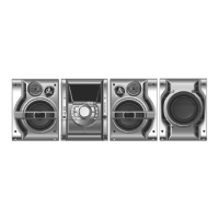
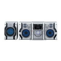
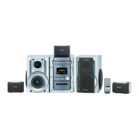
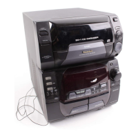
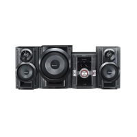
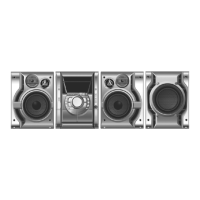
Lists the main system components, including the music center and associated speakers.
Instructions for safe setup, voltage selection, capacitor discharge, and gradual power restoration.
Techniques to prevent static discharge damage and guidelines for handling lead-free solder.
Precautions for handling the traverse deck and laser diode to prevent damage from static electricity.
Lists and illustrates the included accessories such as remote control, antennas, AC cord, and plug adapter.
Explains how to operate the main unit and its remote control, detailing button functions and modes.
Information on the self-diagnostic display, how to enter it, perform tests, clear errors, and interpret codes.
How to set CD test mode, view auto-adjustment results, and enter CD aging test mode for reliability.
Procedures for cassette deck and tuner measurements, adjustments, and alignment points.
A flowchart to diagnose and troubleshoot common problems, guiding through checks for CD playback and mechanism failures.
A flowchart illustrating the sequence for disassembling the main unit's casing and internal parts.
Details on a specific gear used as a jig for servicing operations like disc tray and traverse unit movement.
Step-by-step instructions for removing the top cabinet of the main unit by unscrewing and lifting.
Procedure for removing the CD lid, including steps for opening the disc tray automatically.
Instructions for removing the rear panel by unscrewing and disconnecting wires.
Procedure for removing the CD mechanism unit, involving unscrewing and detaching FFC wires.
Steps to disassemble the main Printed Circuit Board, involving disconnecting FFC wires and connectors.
Procedure for disassembling the sub-power Printed Circuit Board, involving removing screws and connectors.
Steps for disassembling the power Printed Circuit Board, including removing screws and desoldering components.
Instructions for disassembling the transformer PCB and voltage selector, involving screws and breaking joints.
Steps to disassemble the front panel unit, including releasing claws and removing the volume knob.
Procedure for disassembling the deck mechanism unit, involving detaching FFC wires and removing screws.
Steps for replacing the traverse deck unit within the CD mechanism, involving gears and disc tray operation.
Procedure for installing the CD servo PCB after replacement, involving connecting FFC and soldering.
Steps for installing the traverse deck assembly, aligning gears and bosses for proper function.
Procedure for replacing the disc tray, involving removing screws, plates, and PCBS, then installing the tray.
Steps for disassembling and reassembling the mechanism base drive unit, including gears, springs, and PCBs.
Specific procedures for disassembling and reassembling the spindle base unit, involving disc spacers and support plates.
Procedures for installing the loading stopper and reassembling the mechanism base drive unit, focusing on gear installation.
Checks to perform after servicing to ensure proper operation of tray base, spindle, and traverse assemblies.
Procedure for replacing the motor assembly, including notices for installation and connecting components.
Procedure for replacing the pinch roller assembly and head block, involving releasing claws and removing connectors.
Steps for replacing deck motor, capstan belts, and winding belt, including belt installation guidance.
Procedure for replacing the cassette lid assembly, involving lifting a lever and pushing the assembly.
Steps to resolve tape jam issues, involving rotating the flywheel and opening the cassette lid to remove the tape.
Procedures for checking main, transformer, panel, deck, and power PCBs, involving disassembly and connections.
Information on the self-diagnostic display, how to enter it, perform tests, clear errors, and interpret codes.
Procedures to test cassette and CD mechanisms, identifying error codes through specific button presses and modes.
Instructions on clearing error codes, exiting diagnostic mode, and handling power amplifier failure indications.
Detailed explanations of error codes detected for deck mechanism, CD/changer blocks, and power supply issues.
How to set CD test mode, view auto-adjustment results, and enter CD aging test mode for reliability.
How to display the micon software version number and calculated ROM checksum for diagnostic purposes.
A flowchart to diagnose and troubleshoot common problems, guiding through checks for CD playback and mechanism failures.
Procedures for tape speed, bias, and erase voltage adjustments, including measurement conditions and instruments.
Procedure for AM-IF alignment in the tuner section, detailing instrument connection and signal application.
Identifies alignment points for the cassette deck section and tuner section for precise calibration.
A block diagram illustrating the main components and signal flow of the CD optical pickup and related drive circuits.
A table detailing voltage measurements for ICs under different modes (REC, PLAY, STOP) for diagnostic purposes.
Introduction to schematic diagrams, notes on component sensitivity to static electricity, and safety precautions.
Schematic diagram for the CD servo circuit, showing connections for the optical pickup and servo processor IC.
Schematic diagram for the main circuit including the tuner pack, showing connections to ICs like LA1833NMNTLM and LC72131MDTRM.
Schematic diagram for the main circuit, detailing connections for deck controls, motors, and audio processing ICs.
Schematic diagram for the panel circuit, showing connections for buttons, sensors, volume controls, and the FL driver IC.
Schematic diagram of the transformer circuit, illustrating power supply regulation, switching, and protection components.
Schematic diagrams for CD detect, spindle position, CD loading, and sub-power circuits, showing connections to motor drive and power ICs.
Schematic diagram of the power circuit, detailing voltage regulators, headphone muting, and speaker output driver circuits.
Schematic diagrams for the deck circuit and deck mechanism, showing P.B/REC AMP, ALC, and motor control components.
Printed circuit board layout diagram for the CD servo PCB (REPX0443A), showing component placement.
Printed circuit board layout diagram for the main PCB (REPX0442P), showing component placement and connector locations.
Printed circuit board layout diagram for the panel PCB (REPX0474E), showing button, sensor, and connector locations.
Printed circuit board layout diagram for the transformer PCB (REPX0468H), showing transformer and power components.
Layout diagrams for CD detect, spindle position, CD loading, and tuner pack PCBs, showing component placement.
Layout diagrams for power and sub-power PCBs (REPX0447D), showing component placement and connector locations.
Layout diagrams for deck and deck mechanism PCBs (REPX0331D, REPX0321B), showing component and connector placement.
A diagram illustrating the overall wiring connections between various PCBs, including main unit, power, tuner, and CD components.
Visual illustrations and detailed pin functions for ICs, transistors, and diodes used in the system.
Location diagrams and detailed lists for deck mechanism, CD loading mechanism, cabinet, electrical parts, packing materials, and accessories.
| Bluetooth | No |
|---|---|
| CD Player | Yes |
| FM Radio | Yes |
| USB Playback | No |
| Type | Stereo System |
| Number of Channels | 2 |
| Tuner Bands | FM |
| USB Port | No |
| Radio | Yes |
| Speaker Configuration | 2.0 |
| Playable Media | CD |
| Speaker Type | 2-way |