Do you have a question about the Panasonic SA-AK640E and is the answer not in the manual?
Basic safety procedures and recommendations for service personnel.
Specific safety advice regarding the AC power cord and its handling.
Details on identifying and handling lead-free solder.
An overview of the CRS1 CD changer mechanism's design and functionality.
A table detailing various special modes, their descriptions, and key operations.
General cautions and warnings to be observed during disassembly and servicing.
Procedures for replacing specific components on the power PCB.
Steps for removing the pinch roller and head block assembly.
Procedures for checking and repairing the main printed circuit board.
Procedures for adjusting the cassette deck section.
Steps for performing the AM Intermediate Frequency alignment.
Voltage and waveform data for CD servo and main PCBs.
Voltage and waveform data for power and transformer PCBs.
Specific waveform examples for reference during servicing.
Important notes and disclaimers regarding the schematic diagrams.
The schematic diagram for the CD loading circuit.
The layout diagram for the CD loading PCB.
Exploded views of the CD loading mechanism parts.
Specific list of replacement parts for the CD loading mechanism.
Schematic of the deck printed circuit board.
Schematic of the deck mechanism printed circuit board.
Schematic of the power printed circuit board.
Schematic of the transformer printed circuit board.
Schematic of the panel printed circuit board.
Schematic of the main circuit board.
Schematic of the main tuner circuit.
Schematic of the CD servo control circuit.
PCB layout diagram for the deck mechanism circuit board.
Details the functions and operations for tray opening and disc changing.
Basic features and characteristics of the five-disc changer mechanism.
Lists and describes the hardware components of the mechanism.
Explains the different states and operational sequences of the mechanism.
Explains the different modes and procedures for opening the disc trays.
A table detailing the special modes, their functions, and key operations.
Steps for preparing a service jig for unit checks.
Procedures to verify the functionality of the changer unit.
Instructions for setting the unit's trays to the STOCK position for service.
A flowchart detailing the sequence of disassembly steps.
Detailed steps for taking the unit apart.
Instructions for assembling the CD loading unit.
Lists the necessary equipment for performing the ageing and reliability tests.
The schematic diagram for the CD loading circuit.
The layout diagram for the CD loading PCB.
Exploded views of the CD loading mechanism parts.
Specific list of replacement parts for the CD loading mechanism.
| Brand | Panasonic |
|---|---|
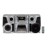
| Model | SA-AK640E |
| Category | Stereo System |
| Language | English |