EasyManua.ls Logo

Panasonic SA-AKX70PH User Manual

Panasonic SA-AKX70PH
135 pages
To Next Page IconTo Next Page
Page #1 background imageLoading...
Page #1 background image
© Panasonic Corporation 2010. All rights reserved.
Unauthorized copying and distribution is a violation
of law.
PSG1004040CE
CD Stereo System
Model No. SA-AKX70PH
SA-AKX70PN
Product Color: (K)...Black Type
TABLE OF CONTENTS
PAGE PAGE
1 Safety Precautions----------------------------------------------- 3
1.1. General Guidelines---------------------------------------- 3
1.2. Before Use (For PH only)-------------------------------- 3
1.3. Caution For Fuse Replacement------------------------ 3
1.4. Before Repair and Adjustment ------------------------- 4
1.5. Protection Circuitry---------------------------------------- 4
1.6. Safety Parts Information --------------------------------- 4
2 Warning-------------------------------------------------------------- 6
2.1. Prevention of Electrostatic Discharge (ESD)
to Electrostatic Sensitive (ES) Devices -------------- 6
2.2. Precaution of Laser Diode------------------------------- 7
2.3. Service caution based on Legal restrictions-------- 8
2.4. Handling Precautions for Traverse Unit --------------9
3 Service Navigation --------------------------------------------- 11
3.1. Service Information-------------------------------------- 11
4 Specifications---------------------------------------------------- 12
5 Location of Controls and Components------------------ 13
5.1. Main Unit Key Button Operation---------------------- 13
5.2. Remote Control Key Button Operation ------------- 14
5.3. Media Information---------------------------------------- 15
6 Self-Diagnostic and Special Mode Setting ------------- 16
6.1. Cold-Start -------------------------------------------------- 16
6.2. Doctor Mode Table--------------------------------------- 17
Notes: Please refer to the original service manual for:
O CD Mechanism Unit (DLS6C), Order No. MD0803034CE
O Speaker system SB-AKX70PN-K, Order No. PSG1004001CE

Table of Contents

Question and Answer IconNeed help?

Do you have a question about the Panasonic SA-AKX70PH and is the answer not in the manual?

Panasonic SA-AKX70PH Specifications

General IconGeneral
TypeMini Hi-Fi System
Speaker Configuration2.0
BluetoothYes
USB PlaybackYes
USB PortYes
FM RadioYes
CD PlayerYes
MP3 PlaybackYes
Number of Discs1
Preset EqualizerYes
Remote ControlYes
Playable formatsCD, CD-R

Summary

1 Safety Precautions

1.1. General Guidelines

General safety guidelines for servicing the equipment.

1.2. Before Use (For PH only)

Voltage selector setting caution for PH models.

1.3. Caution For Fuse Replacement

Precautions related to fuse replacement.

1.4. Before Repair and Adjustment

Safety measures before performing repairs or adjustments.

1.5. Protection Circuitry

Information on the protection circuitry and its function.

1.6. Safety Parts Information

List of safety-critical parts and their importance.

2 Warning

2.2. Precaution of Laser Diode

Safety precautions when handling the laser diode.

2.3. Service caution based on Legal restrictions

Cautions regarding legal restrictions and lead-free solder.

2.4. Handling Precautions for Traverse Unit

Specific handling precautions for the traverse unit and optical pickup.

3 Service Navigation

3.1. Service Information

General information for servicing the model.

4 Specifications

5 Location of Controls and Components

5.1. Main Unit Key Button Operation

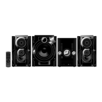
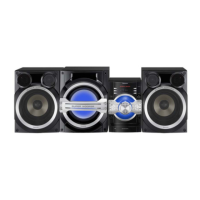
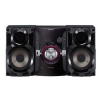
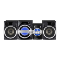
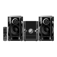
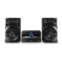
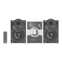
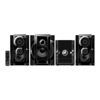
Description of buttons and controls on the main unit.

5.2. Remote Control Key Button Operation

Description of buttons and controls on the remote control.

5.3. Media Information

Information regarding supported media formats like CD and MP3.

6 Self-Diagnostic and Special Mode Setting

6.1. Cold-Start

Procedure for performing a cold-start or initializing to shipping mode.

6.2. Doctor Mode Table

Tables detailing different doctor modes and their operations.

7 Troubleshooting Guide

7.1. Troubleshooting Guide for F61 and/ or F76

Guide for troubleshooting specific error codes F61 and F76.

7.2. Part Location

Location of key parts on various PCBs.

8 Service Fixture & Tools

8.1. Service Tools and Equipment

List of service tools and equipment required for repair.

9 Disassembly and Assembly Instructions

9.1. Disassembly Flow Chart

Flowchart illustrating the disassembly sequence of components.

9.2. Main Components and P.C.B. Locations

Visual guide to the location of major components and PCBs within the unit.

9.3. Disassembly of Top Cabinet

9.4. Disassembly of Tuner P.C.B.

9.5. Disassembly of Front Panel Assembly

9.6. Disassembly of Panel P.C.B.

9.7. Disassembly of Remote Sensor P.C.B.

9.8. Disassembly of CD Open Button P.C.B.

9.9. Disassembly of Jupiter P.C.B.

9.10. Disassembly of Music Port/ Headphone P.C.B.

9.11. Disassembly of CD Lid

9.12. Disassembly of Main P.C.B.

9.13. Replacement of Regulator IC (IC2010)

9.14. Disassembly of Mic P.C.B.

9.15. Disassembly of D-Amp P.C.B.

9.16. Disassembly of SMPS P.C.B.

9.17. Replacement of Switching Regulator IC (IC5701)

9.18. Replacement of Rectifier Diode (D5702)

9.19. Replacement of Regulator Diode (D5801)

9.20. Replacement of Regulator Diode (D5802)

9.21. Replacement of Regulator Diode (D5803)

9.22. Disassembly of CD Mechanism Unit (DLS6C)

9.23. Disassembly of Rear Panel

9.24. Disassembly of Voltage Selector P.C.B. (For PH only)

9.25. Disassembly of CD Servo P.C.B.

9.26. Replacement of Audio Digital Amp IC (IC5000)

9.27. Replacement of Audio Digital Amp IC (IC5200)

9.28. Replacement of Audio Digital Amp IC (IC5400)

10 Replacement of Traverse Unit

10.1. Disassembling Procedures

Procedures for disassembling the traverse unit.

10.2. Assembling Procedure

Procedure for assembling the traverse unit.

11 Service Position

11.1. Checking and Repairing of Main P.C.B.

Procedures for checking and repairing the Main PCB.

11.2. Checking and Repairing of D-Amp P.C.B.

Procedures for checking and repairing the D-Amp PCB.

11.3. Checking and Repairing of Panel P.C.B.

Procedures for checking and repairing the Panel PCB.

11.4. Checking and Repairing of Jupiter P.C.B.

11.5. Checking and Repairing of SMPS P.C.B.

12 Voltage & Waveform Chart

12.1. CD Servo P.C.B.

Voltage values for the CD Servo PCB in different modes.

12.2. Main P.C.B. (1/2)

Voltage values for the Main PCB (part 1).

12.3. Main P.C.B. (2/2)

Voltage values for the Main PCB (part 2).

12.4. Jupiter P.C.B. (1/3)

12.5. Jupiter P.C.B. (2/3)

12.6. Jupiter P.C.B. (3/3)

12.7. Panel P.C.B.

12.8. D-Amp P.C.B.

12.9. SMPS P.C.B.

12.10. Tuner P.C.B.

12.11. Mic P.C.B.

12.12. Waveform Table (1/2)

12.13. Waveform Table (2/2)

13 Illustration of ICs, Transistor and Diode

14 Simplified Block Diagram

14.1. Overall Simplified Block Diagram

High-level block diagram of the system's architecture.

15 Block Diagram

15.1. Servo/System Control

Block diagram illustrating servo and system control functions.

15.3. Audio

Block diagram detailing the audio signal paths and components.

15.4. Power Amplifier

15.5. Power Supply

16 Wiring Diagram

17 Schematic Diagram Notes

18 Schematic Diagram

18.1. CD Servo Circuit

Schematic diagram of the CD servo control circuit.

18.2. Main Circuit

Schematic diagram of the main processing and control circuit.

18.3. Jupiter Circuit

18.4. Panel Circuit

18.5. CD Open Button, Remote Sensor, Tuner & Music Port/Headphone Circuit

18.6. D-Amp Circuit

18.7. SMPS Circuit

18.8. Mic & Voltage Selector Circuit (For PH Only)

19 Printed Circuit Board

19.1. CD Servo, Mic & Voltage Selector P.C.B. (For PH Only)

PCB layout for CD Servo, Mic, and Voltage Selector.

19.2. Main P.C.B.

PCB layout for the Main circuit board.

19.3. Jupiter P.C.B.

PCB layout for the Jupiter circuit board.

19.4. Panel P.C.B.

19.5. CD Open Button, Remote Sensor, Tuner & Music Port/Headphone P.C.B.

19.6. D-Amp P.C.B.

19.7. SMPS P.C.B. (For PH Only)

19.8. SMPS P.C.B. (For PN Only)

20 Terminal Function of ICs

20.1. IC2003 (RFKWMAKX70PN): IC MICRO-PROCESSOR

Terminal functions for the main microprocessor IC.

20.2. IC6901(C0HBB0000057): IC FL Driver

Terminal functions for the FL display driver IC.

21 Exploded View and Replacement Parts List

21.1. Exploded View and Mechanical replacement Part List

Exploded views and mechanical parts list for cabinet components.

21.1.3. Mechanical Replacement Part List

Detailed list of mechanical replacement parts with part numbers.

21.2. Electrical Replacement Part List

Related product manuals