76
11 Service Position
Note: For description of the disassembly procedures, see
the Section 10.
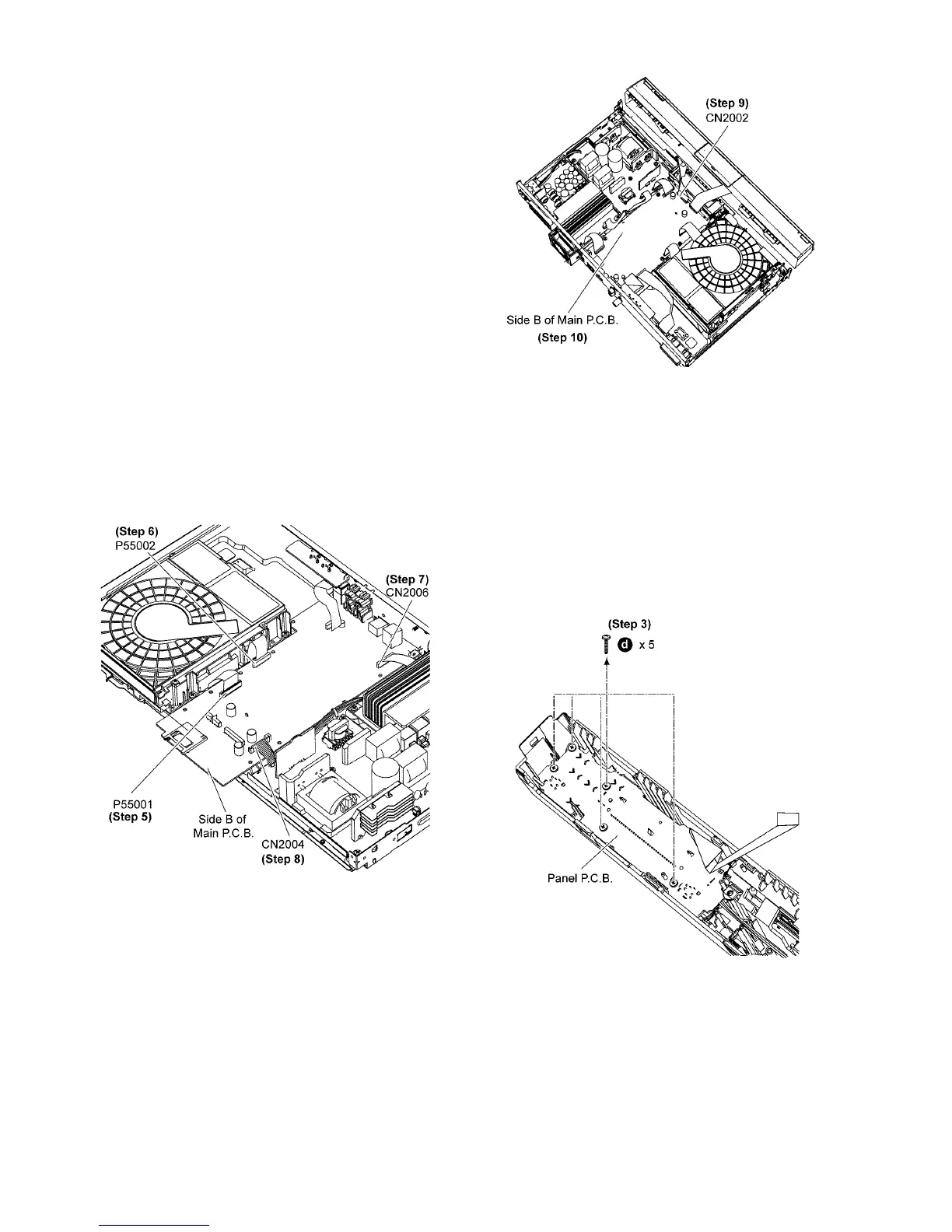
11.1. Checking & Repairing Side B of
Main P.C.B.
Caution:
Pairing of BD Drive and Main P.C.B. as “BD Drive & Main
P.C.B. Assembly” have to be replaced together. If either BD
Drive or Main P.C.B. is changed, BD Drive unit has to carry
out re-adjustment due to alignment data for BD Drive Unit
is stored in the Main P.C.B.
Step 1 Remove Top Cabinet.
Step 2 Remove Front Panel Block Assembly.
Step 3 Remove Front Shield Plate Unit.
Step 4 Remove Main P.C.B. Shield plate.
Step 5 Connect 45P FFC at the connector (P55001) on Main
P. C. B. .
Step 6 Connect 18P FFC at the connector (P55002) on Main
P. C. B. .
Step 7 Connect 18P FFC at the connector (CN2006) on Main
P. C. B. .
Step 8 Connect 10P FFC at the connector (CN2004) on Main
P. C. B. .
Step 9 Connect 22P FFC at the connector (CN2002) on Main
P. C. B. .
Step 10 Proceed to check and repair Side B of Main P.C.B..
11.2. Checking & Repairing Side A of
Main P.C.B.
Caution:
Pairing of BD Drive and Main P.C.B. as “BD Drive & Main
P.C.B. Assembly” have to be replaced together. If either BD
Drive or Main P.C.B. is changed, BD Drive unit has to carry
out re-adjustment due to alignment data for BD Drive Unit
is stored in the Main P.C.B.
Step 1 Remove Top Cabinet.
Step 2 Remove Front Panel Block Assembly.
Step 3 Remove 5 screws.
Step 4 Release 1 catch.
 Loading...