EasyManua.ls Logo

Panasonic SA-CH84M User Manual

Panasonic SA-CH84M
72 pages
To Next Page IconTo Next Page
Page #1 background imageLoading...
Page #1 background image

Table of Contents

Question and Answer IconNeed help?

Do you have a question about the Panasonic SA-CH84M and is the answer not in the manual?
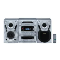
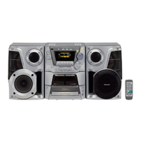
Panasonic SA-CH84M Specifications

General IconGeneral
TypeStereo System
ManufacturerPanasonic
ModelSA-CH84M
Tuner BandsFM/AM
CD PlayerYes
Number of Discs5
Remote ControlYes
CD-R/RW PlaybackYes
USB PortNo
BluetoothNo
Speakers2

Summary

PRECAUTION OF LASER DIODE

Handling Precautions for Traverse Deck

Advises on safe handling of the optical pickup unit to prevent damage.

Location of Controls

Before Repair and Adjustment

Essential pre-service procedures before beginning work.

Grounding for electrostatic breakdown prevention

Procedures for safe grounding to prevent static discharge.

Caution for AC Mains Lead

Operation Checks and Main Component Replacement Procedures

Disassembly of the Loading Unit

Disassembly of the Traverse Unit

Replacement of the Traverse Deck

Measurements and Adjustments

CASSETTE DECK SECTION

Adjustments specific to the cassette deck mechanism.

Head Azimuth Adjustment

Procedure for aligning the tape head azimuth for optimal playback.

Tape Speed Adjustment

Steps to calibrate tape playback speed to the correct frequency.

CD LOADING MECHANISM SECTION

DISC SENSOR ADJUSTMENT

Procedure to adjust the disc sensor for proper CD loading detection.

CD Test Mode

CD AUTOMATICALLY-ADJUSTED RESULT DISPLAY MODE

SERVO MODULE TEST MODE

CHANGER MECHANISM TEST MODE

CHANGER CONTINUOUS OPERATION TEST MODE

Self-Diagnostic Display Function

Cassette Mechanism Test

Diagnostic tests for the cassette mechanism's operational functions.

CD/CD Mega Changer Test

Diagnostic tests for CD changer functions and error detection.

To Display Self-Diagnostic Result

Instructions on how to view error codes and diagnostic results.

Interpretation of error codes

Block Diagram - Optical Pickup

Block Diagram - Servo System

Block Diagram - Tuner Circuit

Block Diagram - Cassette Deck Circuit

Block Diagram - Input Selector and Audio Amplifier

Block Diagram - Speaker Output and Supporting Circuits

Terminal Functions Of ICs

IC701 (AN8835SBE1) Servo Amplifier

Detailed pin functions for the Servo Amplifier IC.

IC703 (AN8389SE1) Motor Driver

Pin functions for the motor driver IC.

Schematic Diagram - Motor Circuits

Importance safety notice

DECK CIRCUIT

MECHANISM (DECK 1) CIRCUIT

MECHANISM (DECK 2) CIRCUIT

SERVO CIRCUIT

TUNER CIRCUIT (E,EB,EG)

TUNER PACK CIRCUIT (GN)

TUNER CIRCUIT (GN)

J POWER CIRCUIT

L CONTROL CIRCUIT

S MAIN P.C.B.

B Tuner P.C.B.

J Power P.C.B.

L Control P.C.B.

G Deck P.C.B.

Wiring Connection Diagram

Mechanism Parts Location (RAA3404)

Mechanism Parts List

Loading Mechanism Parts List

Loading Mechanism Parts Location

Cabinet Parts Location

Replacement Parts List (Page 63)

Replacement Parts List (Page 64)

Replacement Parts List (Page 65)

Replacement Parts List (Page 66)

Resistors & Capacitors (Page 68)

Resistors & Capacitors (Page 69)

Resistors & Capacitors (Page 70)

Resistors & Capacitors (Page 71)

Resistors & Capacitors (Page 72)

Related product manuals