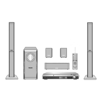
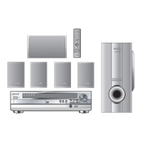
Do you have a question about the Panasonic SA-HT540E and is the answer not in the manual?
| System Type | Home Theater System |
|---|---|
| Audio Channels | 5.1 channels |
| Total Power Output | 1000 W |
| DVD Player | Yes |
| DVD Player / Recorder Type | DVD Player |
| Playable File Formats | MP3, WMA, JPEG |
| USB Playback | Yes |
| USB Port | 1 |
| Surround Sound Formats | Dolby Digital, DTS |
| Tuner Bands | FM/AM |
| Radio Tuner | Yes |
| Remote Control | Yes |
| Playable Disc Types | DVD, CD |
| Audio Formats Supported | MP3, WMA |
| Speaker Configuration | 5.1 |
| Video Output | Composite video, Component video |
| Number of Speakers | 6 (5 satellite speakers + 1 subwoofer) |
| Output Power | 100 W per channel |
Details power source, dimensions, mass, and general electrical parameters of the unit.
Provides RMS output power ratings for Dolby Digital mode and at specific frequencies.
Lists FM tuner specifications including frequency range, sensitivity, and terminals.
Details AM tuner frequency range and sensitivity specifications.
Specifies the type and sensitivity for the phone jack terminal.
Lists compatible disc types for playback, including DVD and CD formats.
Details video system, signal system, and composite video output specifications.
Provides essential guidelines for safe servicing procedures and part replacement.
Outlines precautions for discharging capacitors and gradual power restoration.
Explains the function of protection circuitry and conditions indicating its operation.
Details techniques to prevent damage to sensitive electronic components from static electricity.
Provides critical safety information and handling precautions for the laser diode.
Explains the properties and handling of lead-free solder used in the unit.
Offers safety advice regarding the AC power cord and plug, including fuse replacement.
Provides guidelines for safely handling the optical pickup unit and preventing ESD damage.
Illustrates and explains the functions of each button on the remote control.
Describes the operational functions of buttons located on the main unit.
Details supported disc formats, file types, and media handling precautions.
Explains how to register and play DivX VOD content, including device registration.
Summarizes available service modes, player button combinations, and their applications.
Provides detailed descriptions of service modes, FL display, and key operations.
Explains how to perform self-diagnosis and tilt adjustment for the optical pickup unit.
Lists DVD error codes, diagnosis contents, descriptions, and automatic FL display.
Describes how to set and cancel the sales demonstration lock function to prevent disc loss.
Covers essential precautions for DVD player repair, recovery, and firmware updates.
Provides a visual flowchart outlining the sequence for disassembling major components.
Illustrates the location of main internal components and printed circuit boards (P.C.B.s).
Step-by-step instructions for removing the top cabinet of the unit.
Procedure for opening the DVD lid to manually remove a disc.
Instructions for disassembling the front panel assembly.
Details the process for disassembling the Music Port, FL, and Top Button P.C.B.s.
Step-by-step guide for disassembling the DVD mechanism unit.
Instructions for removing the DVD module P.C.B.
Procedure for removing the rear panel of the unit.
Instructions for removing the Scart P.C.B.
Details the process for removing the main P.C.B.
Step-by-step guide for disassembling digital amplifier ICs.
Instructions for removing regulator ICs.
Procedure for disassembling the switch regulator IC.
Describes specific positions for servicing the DVD Module and Main P.C.B.
Outlines the overall procedure for disassembling the DVD mechanism unit.
Lists necessary tools, equipment, and test discs for measurements and adjustments.
Highlights key considerations for optical and electrical adjustments.
Provides guidelines for proper storage and handling of test discs to ensure accuracy.
Details the procedure for optical pickup tilt adjustment and screw locking.
Presents voltage values for various points on the DVD module P.C.B. during operation.
Provides voltage readings for different points on the main P.C.B.
Lists voltage values for FL, Scart, and Tray Loading P.C.B.s.
Illustrates typical waveforms for various ICs and signals within the unit.
Detailed circuit diagram for the DVD module, including optical pickup.
Circuit diagram illustrating the main unit's power and control functions.
Circuit diagrams for FL display, Music Port, Top Button, Tuner, and Tray Motor.
Detailed circuit diagram for the Scart connection and associated components.
Top and bottom views of the DVD module P.C.B. showing component placement.
Layout diagram for the Main/Power and Tuner Extent P.C.B.
Layouts for the Music Port, Top Button, FL, Scart, and AC Inlet P.C.B.s.
Layout diagram for the Tray Loading P.C.B.
Guide to diagnosing common problems with the DVD traverse unit and checking components.
Guidance for troubleshooting issues related to the power supply circuit.
Block diagram of the DVD unit showing internal functional blocks and interfaces.
Block diagram illustrating signal flow for DVD 5.1ch analog audio playback.
Block diagram showing signal flow for 2-channel analog audio input.
Block diagram detailing the power supply circuits and voltage rails.
Block diagram illustrating the Switched-Mode Power Supply (SMPS) operations.
Description of the terminal functions for the system control microprocessor IC.
Diagram showing the locations of cabinet parts and their corresponding numbers.
Illustrates the packaging arrangement of the unit and its accessories.
Comprehensive list of all components, their part numbers, and descriptions.





 Loading...