EasyManua.ls Logo

Panasonic SA-HT540EE User Manual

Panasonic SA-HT540EE
111 pages
To Next Page IconTo Next Page
Page #1 background imageLoading...
Page #1 background image
lGeneral
Power Source:
A
C 230V, 50Hz
Power consumption: 115 W
Dimensions (W×H×D): 430×60×354 mm
Mass: 3.35kg
lAmplifier section
RMS Output Power: Dolby Digital Mode
lTotal RMS Dolby Digital
mode Power:
850 W
At 1kHz and total harmonic of 10%
lFront: 110 W/ Channel (3)
lCenter: 225 W/ Channel (6)
lSurround: 90 W/ Channel (4)
At 100Hz and total harmonic of 10%
lActive subwoofers: 225 W/ Channel (6)
DIN Output Power: Dolby Digital Mode:
lTotal DIN Dolby Digital mode Power:
440 W
At 1kHz and total harmonic of 1%
lFront: 80 W/ Channel (3)
lCenter: 75 W/ Channel (6)
© 2006 Panasonic AVC Networks Singapore Pte.
Ltd. All rights reserved. Unauthorized copying and
distribution is a violation of law.
SA-HT540EE
Colour
(S).......................Silver Type
lSurround: 65 W/ Channel (4)
At 100Hz and total harmonic of 1%
lSubwoofer: 75 W/ Channel (6)
lPreset Memory: FM 15 stations
AM/MW 15 stations
lFM tuner section (FM)
Frequency Range: 87.5-108.0MHz
(50kHz step)
Sensitivity: 2.5µV (IHF)
S/N 26dB
2.2µV
Antenna Terminals:
75 (unbalanced)
lAM tuner section (AM/MW)
Frequency Range:
522-1629kHz (9kHz step)
AM Sensitivity S/N 20dB at
999kHz:
560µV/m
lPhone jack:
Terminal: Stereo 3.5 mm jack
lMic jack:
Sensitivity: 0.7mV (1.2k)
Terminal: Mono 6.3 mm jack (1 system)
lFront M. Port:
DVD Home Theater Sound System
Specifications
ORDER NO.MD0605176C3

Table of Contents

Question and Answer IconNeed help?

Do you have a question about the Panasonic SA-HT540EE and is the answer not in the manual?
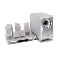
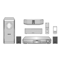
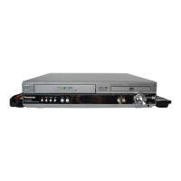
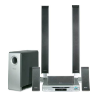
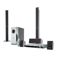
Panasonic SA-HT540EE Specifications

General IconGeneral
TypeHome Theater System
Speaker Configuration5.1 channel
DVD PlayerYes
USB PlaybackYes
Audio Formats SupportedDolby Digital, DTS
Dolby DigitalYes
DTSYes
CD Playback FormatsCD, CD-R, CD-RW
AM/FM TunerYes
HDMI Output1
BluetoothNo
Video Formats SupportedMPEG2, DivX
DVD Playback FormatsDVD-R, DVD-RW

Summary

Safety Precautions

1.1. General Guidelines

General safety guidelines for servicing equipment to ensure safe operation and maintenance.

1.2. Before Repair and Adjustment

Essential precautions and steps before performing any repair or adjustment procedures.

Prevention of Electro Static Discharge (ESD)

Precaution of Laser Diode

Handling Precautions for Traverse Unit

5.1. Optical Pickup Unit Handling

Specific handling instructions for the optical pickup unit to prevent static discharge damage.

5.2. Grounding for Electrostatic Breakdown Prevention

Methods for grounding to prevent electrostatic discharge during servicing operations.

Self-Diagnosis and Special Mode Settings

8.2. Service Mode Table 1

Details of Service Mode Table 1 for diagnostics and adjustments.

8.2. Service Mode Table 2

Details of Service Mode Table 2 for firmware version and region checks.

8.2. Service Mode Table 3

Details of timer checks within Service Mode Table 3.

8.2. Optical Pick-Up Self-Diagnosis

Procedure for performing self-diagnosis on the optical pickup unit.

8.3. DVD Self Diagnostic Function - Error Codes

Guide to DVD self-diagnostic error codes for troubleshooting.

8.3.1. Error Code Table 1

Table listing DVD error codes U11 through F504 and their descriptions.

8.3.2. Error Code Table 2

Table listing DVD error codes F505 through F701 and their descriptions.

8.3.3. Error Code Table 3

Table listing DVD error codes F702 through U701 and their descriptions.

8.5.1. Recovery After DVD Player Repair

Procedures for drive recovery after DVD player repair.

8.5.2. Firmware Version-Up Procedure

Instructions for updating the DVD player's firmware.

8.5.3. DVD Module Reset Procedure

Procedure for resetting the DVD module after component replacement.

Assembling and Disassembling

Service Position

Assembly and Disassembly of Mechanism Unit

11.1.5. Optical Pickup Unit Disassembly

Steps for disassembling the optical pickup unit.

Measurements and Adjustments

12.2. Important points in adjustment

Key considerations before performing adjustments.

12.2.1. Important points in optical adjustment

Key considerations before performing optical adjustments.

12.2.2. Important points in electrical adjustment

Key considerations before performing electrical adjustments.

12.4. Optical adjustment

General overview of optical adjustment procedures.

12.4.1. Optical pickup tilt adjustment

Detailed procedure for optical pickup tilt adjustment.

12.4.1.1. Adjustment procedure

Step-by-step guide for the optical pickup tilt adjustment.

12.4.1.2. Important points

Crucial points to note during optical pickup tilt adjustment.

12.4.1.3. Check after adjustment

Procedure to verify the success of the optical adjustment.

Voltage and Waveform Chart

Wiring Connection Diagram

Block Diagram

Schematic Diagram

Printed Circuit Board

Basic Troubleshooting Guide

21.1. Traverse Unit (DVD Module P.C.B.) Troubleshooting

Guide to troubleshooting common issues with the traverse unit.

Overall Block Diagram (HT540)

Terminal Function of ICs

Exploded Views

Replacement Parts List

Related product manuals