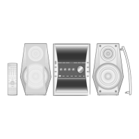
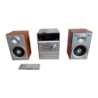
This document describes the SA-PM37MD MD Stereo System, a silver-type audio system designed for the Great Britain area. It includes sections for tape, CD, and MD mechanisms, along with general specifications, operational procedures, troubleshooting, and parts lists.
Function Description
The SA-PM37MD is a comprehensive MD Stereo System that integrates multiple audio playback and recording functionalities. It features an amplifier section, FM/AM tuner, cassette deck, CD player, and MD recorder/player. The system is designed for home audio use, offering various input and output options, including USB and digital optical input.
Important Technical Specifications
- Amplifier Section:
- RMS Power Output (10% total harmonic distortion): 15 W per channel (6 Ω) for LOW, 3 W per channel (6 Ω) for HIGH.
- Total BI-AMP Power: 18 W per channel.
- PMPO: 160 W.
- Input Sensitivity: AUX (500 mV), P-MD (160 mV), USB (Based on USB Rev. 1.0), OPT-IN (Digital Optical Input).
- Input Impedance: AUX (30 kΩ), P-MD (5 kΩ).
- Output Impedance: Headphone (16-32 Ω).
- FM Tuner Section:
- Frequency Range: 87.50-108.00 MHz (0.05 MHz steps).
- Sensitivity: 16.3 dBf (1.8 µV, IHF’58).
- Antenna Terminals: 75 Ω (unbalanced).
- AM Tuner Section:
- Frequency Range: 522-1629 kHz (9 kHz steps).
- Sensitivity (S/N 20 dB): 500 µV/m.
- Cassette Deck Section:
- Track System: 4 track, 2 channel.
- Heads: Record/playback (Solid permalloy head), Erasure (Double gap ferrite head).
- Motor: DC servo motor.
- Recording System: AC bias 100kHz.
- Erasing System: AC erase 100kHz.
- Tape Speed: 4.8 cm/sec.
- Overall Frequency Response (-6dB at Deck Out): Type I (Normal) 35 Hz - 14 kHz, Type II (High) 35 Hz - 14 kHz.
- Wow and Flutter: 0.18 % WRMS.
- CD Section:
- Sampling Frequency: 44.1kHz.
- Decoding: 16 bit linear.
- Beam Source: Semiconductor laser.
- Wavelength: 780 nm.
- Number of Channels: 2 channels stereo.
- S/N Ratio (SP OUT): 70 dB (JIS A).
- Wow and Flutter: Below measurable limit.
- Digital Filter: 8 fs.
- D/A Converter: MASH (1 bit DAC).
- MD Section:
- System: MiniDisc Digital Audio System.
- Recording: Magnetic field modulation, direct overwrite.
- Reading: Non-contact optical system with semiconductor laser (Wavelength = 780nm).
- Sampling Frequency: 44.1 kHz.
- Coding System: ATRAC/ATRAC3 (MDLP).
- Number of Channels: 2 channels stereo.
- Wow and Flutter: Below measurable limit.
- 80 min MD Disc Use: 80 min (SP), 160 min (LP2), 320 min (LP4).
- USB DAC Section: Based on USB Rev. 1.0.
- General:
- Power Supply: AC 230-240 V, 50 Hz.
- Power Consumption: 60 W.
- Standby: 0.9 W.
- Dimensions (WxHxD): 165.4x228x315 mm.
- Mass: 4.8 kg.
Usage Features
The system offers a self-diagnostic display function to aid in servicing and maintenance. This function allows users or technicians to check for errors in the cassette deck, CD, and MD sections. It requires specific cassette tapes (blank Cr02 and normal music tape) and the remote controller to enter and navigate the diagnostic mode. Error codes are displayed to indicate faulty parts or operations.
Maintenance Features
- Before Repair and Adjustment: Always disconnect AC power and discharge power supply capacitors (C607, C635, C637) through a 10 Ω, 5W resistor to ground. Avoid short-circuiting directly to prevent damage to solid-state devices.
- Protection Circuitry: The unit includes protection circuitry that may activate if conditions like shorted speaker wires or low-impedance speakers are detected. If activated, turn off the power, identify and correct the problem, then turn the power back on after one minute.
- Accessories: The system comes with a remote control transmitter, FM indoor antenna, AC mains lead, and power plug adapter. An AM loop antenna is also included.
- Self-Diagnostic Display Function: This feature helps identify problems by displaying error codes for the cassette deck, CD, and MD sections.
- Clearing Self-Diagnostic Memory: Errors stored in memory can be cleared by holding down the [STOP] button for 5 seconds or more in self-diagnostic mode.
- Displaying Self-Diagnostic Results: Specific procedures are outlined for each section (Cassette Deck, CD, MD) to display diagnostic keys or a "TEST" message if no errors are found.
- Handling Precautions for Traverse Deck (CD/MD): The laser diode in the optical pickup is extremely sensitive to static electricity and electrical shock.
- Avoid subjecting the optical pickup to static electricity.
- The short land between specific pins on the flexible board (FFC) is shorted with solder to prevent laser diode damage; this solder must be removed before making connections.
- Do not apply excessive stress to the flexible board.
- Do not turn the variable resistor for laser power adjustment, as it is factory-adjusted.
- Grounding for Electrostatic Breakdown Prevention:
- Human Body Grounding: Use an anti-static wrist strap to discharge static electricity from your body.
- Work Table Grounding: Place a conductive sheet or steel sheet on the work area and ground it.
- Caution: Static electricity from clothes will not be grounded through the wrist strap, so avoid contact between clothes and the traverse deck.
- Precaution when Replacing Optical Pickup: The traverse has a short point shorted with solder to protect the laser diode. This solder must be removed before making connections.
- Precaution of Laser Diode: This product utilizes a laser diode that emits invisible laser radiation when "ON." Wavelength is 780 nm, and maximum output radiation power from the pick-up is 100 µW/VDE.
- Do not disassemble the optical pick-up unit.
- Do not adjust the variable resistor on the pick-up unit.
- Do not look at the focus lens with optical instruments.
- Do not stare at the pick-up lens for extended periods.
- Measurement and Adjustments:
- Tuner/CD Sections: No adjustment required.
- Cassette Deck Section: Procedures for head azimuth adjustment and tape speed adjustment are detailed, requiring specific test tapes (QZZCFM, QZZCWT) and equipment like an oscilloscope and frequency indicator. Bias voltage check procedures are also provided.
- MD Section: Detailed procedures for laser power adjustment and measurement of offset, RAM, and ROM are included. This section emphasizes precautions due to the higher laser beam level compared to CD players. Specific ROM and RAM discs are required for these adjustments.
- Troubleshooting Flowcharts: Comprehensive flowcharts are provided for MD Section and CD Section circuits to guide technicians through diagnostic steps based on symptoms and measurements.
- Parts Location and Replacement Parts List: The manual includes diagrams and lists for deck mechanism, MD mechanism, CD loading mechanism, cabinet, and integrated circuits, along with important safety notices regarding component replacement.