6
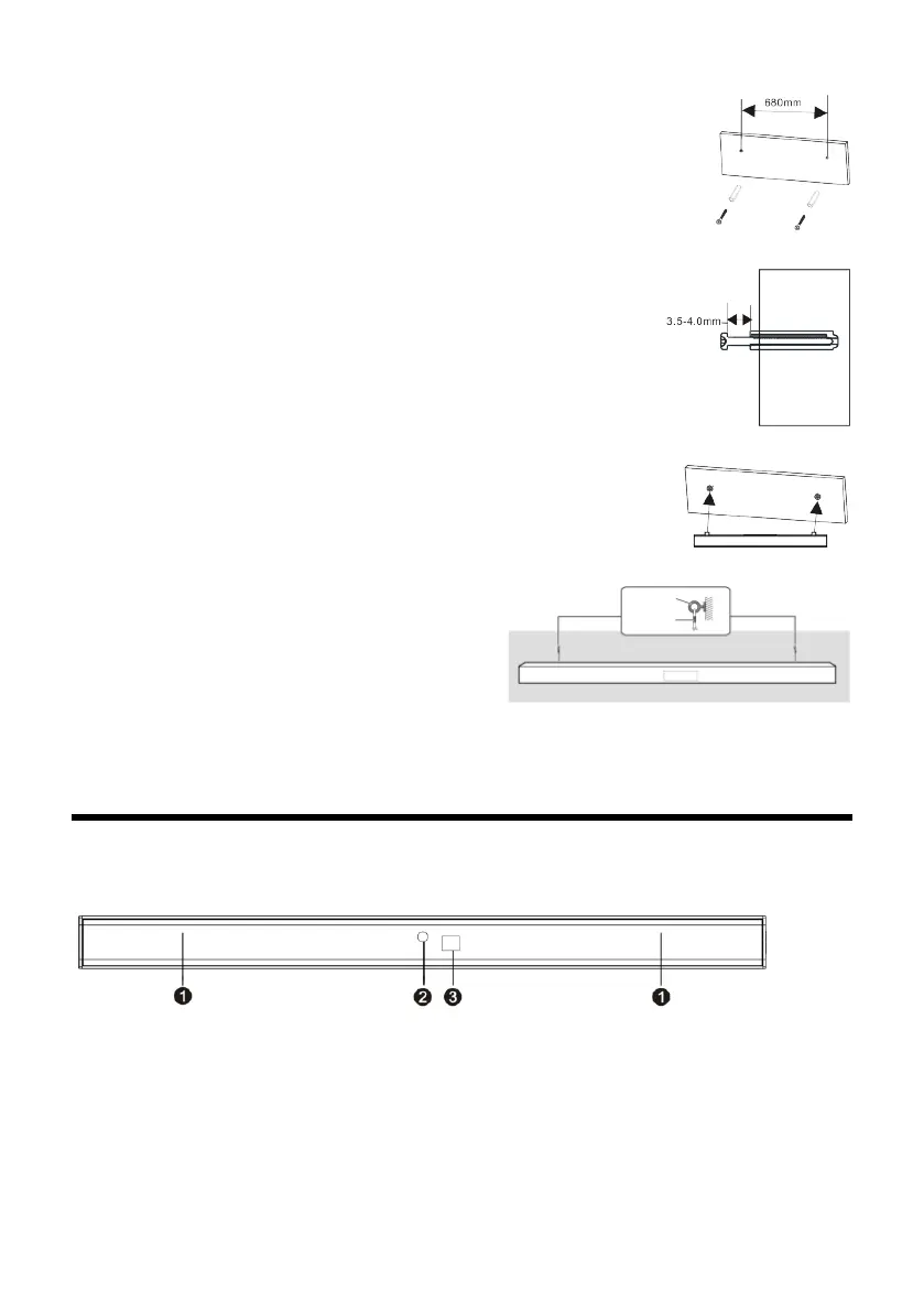
1. Drill the two holes (about 6mm diameter) in the wall
keeping 680 mm distance between the drill holes, as
shown in the picture on the right. Insert the two plugs
supplied into the drilled holes and then insert two screws
(supplied) into the holes and tighten. As shown in the
picture on the right (diagram1).
2. Take care to leave 4 mm between the screw heads and
the wall. As shown in the picture on the right (diagram 2).
3. Hang the assembled sound bar on the screw set in the
wall. As shown in the picture on the right (diagram3).
4. Attach the fall prevention cord (not supplied)
to the screw eyes, secure the cord to the wall,
making sure that the slack of the cord is
minimal. As shown in the lower picture
(diagram4).
Note: Use a cord that is capable of supporng over 30kg (with a diameter of about 1.5mm).
Panel
FRONT PANEL:
SPEAKER: Amplifier of the unit.
INDICATOR LIGHT: Show the units current mode status.
REMOTE SENSOR: Point the remote control at the remote
control sensor, away from obstacles and within the
operation range.
Indicator light
Red: In STANDBY mode.
Blue: In Bluetooth mode.
Green: In LINE IN mode.
Yellow: In Optical mode.
Purple: In HDMI ARC mode.
 Loading...