INSTRUCTION MANUAL
SU-7
MOUNTING
2
MS-DIN-2
2
Attached amplifier mount-
ing bracket or 35mm width
DIN rail.
1
2
1
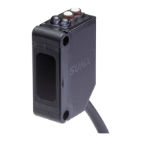
PART DESCRIPTION
1
Mode selection switch
Timer adjuster (Note)
Stable operation indicator (Green)
Operation indicator (Red)
Sensitivity setting buttons
ON button
OFF button
SU-75
HOW TO CONNECT THE SENSOR HEAD
3
<Cutting cable>
SU-CT1
Holes for
cutting
Inlet for
stripping
Top position Middle position
There is a stopping
feel at the position
shown by the arrow.
SU-CT1
Bottom view of SU-CT1
Stopper
Cable
Insert till
the end.
Not good
SU-CT1
SU-CT1
SU-CT1
I/O CIRCUIT DIAGRAMS
4
<NPN output type>
<PNP output type>
+
-
12 to 24V DC
±10%
Load
Load
Internal circuit Users’ circuit
(Brown) +V
Main circuit
(Blue) 0V
100mA max.
50mA max.
(Orange)
Self-diagnosis output
If a disable switch is provided here,
it prevents wrong setting.
(Black) Sensing output
(Pink) Input 1 (Note)
(Violet) Input 2 (Note)
5V
5V
Color code
(Blue) 0V
100mA max.
50mA max.
(Orange) Self-diagnosis output
(Black) Sensing output
+
-
12 to 24V DC
±10%
Load
Load
Internal circuit Users’ circuit
(Brown) +V
Main circuit
Color code
SU-7
SU-7P
SU-75 SU-77 SU-79
1
Case cover
5 to 9mm 2
5 to 9mm
Shielded wire
Cable sheath
Cable core
Cable core
No need to strip.
Not good
Wire
Black
Cable
inlet
Gray
Case cover
6
Cable end
Seal
Seal
BlackGray
3
4
5