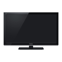
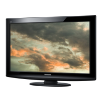
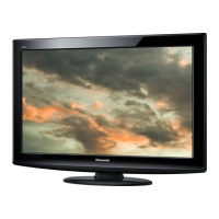
Do you have a question about the Panasonic TC-L32XM6H and is the answer not in the manual?
General guidelines for servicing and repairs, including safety measures.
Procedure for checking leakage current with the unit unplugged.
Procedure for checking leakage current with the unit plugged in.
Techniques to prevent component damage from static electricity.
Information on lead-free solder usage and precautions.
Diagram showing the layout of main circuit boards (A-Board, K-Board, P-Board).
Instructions on accessing the service mode using the remote control.
Objective of entering the service mode for adjustments and checks.
Explanation of remote control button functions within service mode.
Procedure to exit the service mode.
Details of adjustable parameters within the service mode.
Information and access to the Service Tool utility.
Steps to access the SRV-TOOL utility.
Explanation of the SOS History display and its meaning.
Information on displaying the unit's power on time and count.
How to exit the SRV-TOOL utility.
Procedure for performing a drive check using a USB HDD.
Configuration options for restricting functions in hotel environments.
The objective of the Hotel mode feature.
Steps to enter the Hotel mode setup menu.
How to exit the Hotel mode setup menu.
Detailed explanation of Hotel mode settings.
Instructions for copying data to and from a USB memory device.
Reasons for using USB data copy (board replacement, hotel setup).
Steps to prepare a USB memory stick for data copy.
Procedure for copying data from the TV to a USB memory device.
Procedure for copying data from USB memory to the TV.
Procedure for checking IIC bus line integrity.
Steps to access the IIC bus line check.
How to view self-check results on the screen.
How to perform self-check and reset to factory settings.
How to exit the IIC bus line check mode.
Example screen display of the self-check results.
Identifies components to check if the self-check fails (NG).
Table detailing power LED blink codes and corresponding faults.
Procedure to enter and use the LCD Panel test mode for diagnosis.
A flowchart illustrating the disassembly sequence of the unit.
Detailed steps for disassembling various parts of the TV.
Steps to remove and replace the TV pedestal.
Steps to remove and replace the rear back cover.
Steps to remove and replace the key button bracket.
Steps to remove and replace the P-Board (Power Board).
Steps to remove and replace the A-Board (Main Board).
Steps to remove and replace the speaker units.
Steps to remove and replace the speaker bracket.
Steps to remove and replace the bottom metal bracket.
Steps to remove the LCD mounting, cabinet, and LCD panel.
Steps to remove and replace the K-Board.
Table listing output voltages and test points for the P-Board.
Table listing output voltages and test points for the A-Board.
A high-level block diagram of the TV's internal components and connections.
Part one of the detailed block diagram, showing power and main board connections.
Part two of the detailed block diagram, showing tuner, audio, and interface connections.
Important cautions regarding flexible cable assembly and locking.
Diagram showing proper routing and connection of internal wires and cables.
