Do you have a question about the Panasonic TC-L42U12 and is the answer not in the manual?
Techniques to prevent damage to sensitive electronic components from static electricity.
Instructions on accessing the service mode using remote control and unit buttons.
A chart correlating power LED blinking patterns to specific error conditions.
A flowchart to diagnose and resolve "No Power" issues based on power LED status.
Tables showing test points, voltages, and specifications for P-board and A-board.
Part 1 of 11 of the A-Board schematic, showing IC8001 and related components.
Part 2 of 11 of the A-Board schematic, detailing EEPROM and Flash ICs.
Part 3 of 11 of the A-Board schematic, covering power supply and analog ASIC.
Part 4 of 11 of the A-Board schematic, showing IC2301 and related circuits.
Part 5 of 11 of the A-Board schematic, detailing digital audio out and control panel connections.
Part 6 of 11 of the A-Board schematic, focusing on IC1102 and IC1103.
Part 7 of 11 of the A-Board schematic, showing IC4202 and LVDS TX.
Part 8 of 11 of the A-Board schematic, detailing HDMI3 connections.
Part 9 of 11 of the A-Board schematic, showing Peaks AVC and PC RGB connections.
Part 10 of 11 of the A-Board schematic, covering power supply and analog inputs.
Part 11 of 11 of the A-Board schematic, showing tuner and analog connections.
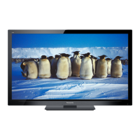
| Screen Size | 42 inches |
|---|---|
| Resolution | 1920 x 1080 |
| Display Type | LCD |
| Backlight Type | CCFL |
| HDMI Ports | 3 |
| USB Ports | 1 |
| Audio Output | 10W x 2 |
| Weight | 45.5 lbs |
| Aspect Ratio | 16:9 |
| Response Time | 6.5 ms |
| Component Video Inputs | 1 |
| Composite Video Inputs | 1 |
| PC Input | 1 |
| Refresh Rate | 60 Hz |
| Inputs | HDMI, Component, Composite, PC |
| Sound Output | 20W |
