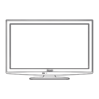
8 9
Quick Start
Guide
Accessories/Optional Accessory
Accessories
Assembly screws
(4 of each)
A
XSS4+16FJK
M4 × 16
B
XYN4+F12FJK
M4 × 12
Bracket (1)
Base (1)
Accessories
A
Screws (2)
XSN3+4FJ
M3 × 4
B
Wood screw (4)
THM2AB001
C
Bit (for pedestal) (1)
Assembling the pedestal
Fix securely with assembly screws
A
. (Total 4 screws)
Tighten screws firmly.
A
Bracket
Front
Base
(Image: TBL2AX0032)
Set-up
Fix securely with assembly screws . (Total 4 screws)
Tighten screws firmly.
B
B
Foam mat or thick
soft cloth
WARNING
Do not disassemble or modify the pedestal.
Otherwise the TV may fall over and become damaged, and personal injury may result.
Caution
Do not use any other TV and displays.
Otherwise the TV may fall over and become damaged, and personal injury may result.
Do not use the pedestal if it becomes warped or physically damaged.
If you use the pedestal when it is physically damaged, personal injury may result. Contact your nearest Panasonic
Dealer immediately.
During set-up, make sure that all screws are securely tightened.
If sufficient care is not taken to ensure screws are properly tightened during assembly, the pedestal will not be strong
enough to support the TV, and it might fall over and become damaged, and personal injury may result.
Antenna terminal Pin terminals HDMI terminal
greenbluered
green
Firmly tighten by hand.
Match colors of plugs and terminals.
Insert firmly.
Insert firmly.
Reference of connection
Attaching the pedestal to TV
•
Place the TV set in a position where it will not protrude from the table when swiveled.
•
Make sure there is enough space between the TV set and wall, so that when the TV set is swiveled it does not hit the wall.
Accessories/Optional Accessory
(Continued)
Location
Place the TV at a comfortable distance for viewing. Avoid placing it where sunlight or other bright light (including reflections)
will fall on the screen. Use of some types of fluorescent lighting can reduce remote control transmitter range. Adequate
ventilation is essential to prevent an internal component failure. Keep away from areas of excessive heat or moisture.
Adjust the stand to your desired angle.
The stand angle can be rotate 30°/60°/90° to the right/left. (see Control rotation angle)
ab
[Rotation angle: 30°]
TH-32LRU20 a: 9.8 ” (248 mm)
b: 7.6 ” (193 mm)
TH-37LRU20 a: 11.0 ” (279 mm)
b: 8.8 ” (222 mm)
TH-42LRU20 a: 12.5 ” (316 mm)
b: 9.8 ” (248 mm)
ab
[Rotation angle: 60°]
TH-32LRU20 a: 15.0 ” (381 mm)
b: 12.8 ” (323 mm)
TH-37LRU20 a: 17.1 ” (433 mm)
b: 14.7 ” (373 mm)
TH-42LRU20 a: 19.0 ” (483 mm)
b: 16.5 ” (418 mm)
ab
[Rotation angle: 90°]
TH-32LRU20 a: 17.3 ” (439 mm)
b: 14.2 ” (360 mm)
TH-37LRU20 a: 19.7 ” (500 mm)
b: 16.4 ” (416 mm)
TH-42LRU20 a: 21.9 ” (555 mm)
b: 18.4 ” (467 mm)
Control rotation angle
The rotation angle can be controlled at 30° or 60°.
It is not necessary to attach the screws for the 90° angle rotation.
Temporarily remove the 5 screws shown below.
Attach
A
screws (2) to each angle control position.
Swivel plate
[Bottom view]
1
2
5
4
3
[Front of swivel plate] [Back of swivel plate]
[For 30°]
[For 60°]
Set-up
6.5” (165 mm)
6.1” (155 mm)
5.7” (144 mm)
a
b
0.079” – 0.091”
(2 – 2.3 mm)
Use the specialized bit
(supplied) in position
a
,
and screw in
B
wood
screw (2).
[Back of fixed plate]
Align the swivel hole in the bottom of the
swivel plate with
B
wood screw that was
screwed in previously, and place the TV
set onto the swivel plate.
Slide the TV set forwards until it stops,
then fix it in place.
b
Lastly, use the
C
specialized bit to fix
B
Wood screw in place.
[View from above]
 Loading...
