19
7 Disassembly and Assembly Instructions
7.1. Remove the rear cover
1. See Service Hint (Section 3)
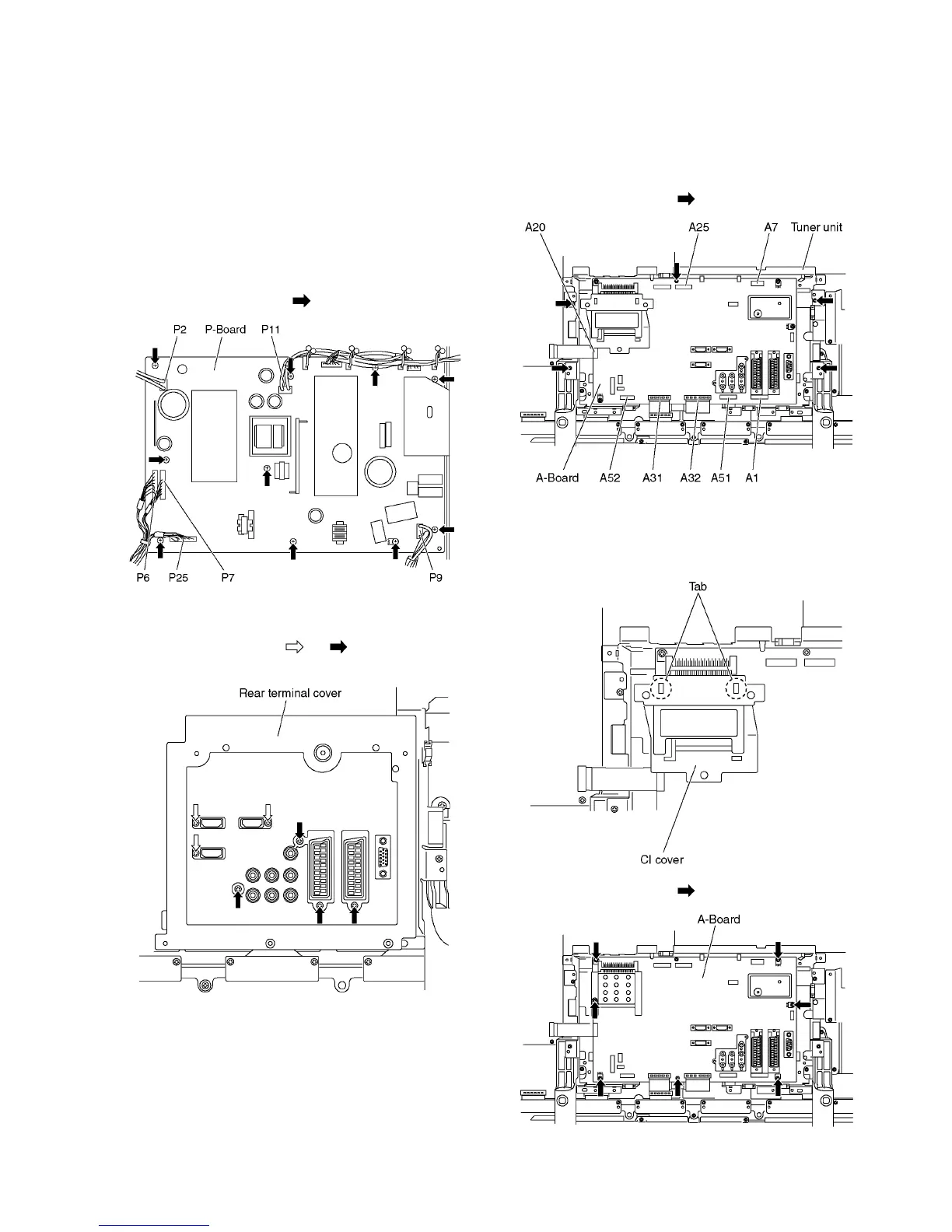
7.2. Remove the P-Board
Caution:
To remove P.C.B. wait 1 minute after power was off for dis-
charge from electrolysis capacitors.
1. Unlock the cable clampers to free the cable.
2. Disconnect the connectors (P2, P6, P7, P9, P11, P12 and
P25).
3. Remove the screws (×10 ) and remove the P-Board.
7.3. Remove the rear terminal cover
1. Remove the screws (×3 , ×4 ).
2. Remove the rear terminal cover.
7.4. Remove the Tuner unit
1. Unlock the cable clampers to free the cable.
2. Disconnect the connectors (A1, A7, A12, A25, A31, A32,
A51, A52).
3. Remove the screws (×5 ) and remove the tuner unit.
7.5. Remove the A-Board
1. Remove the tuner unit. (See section 7.4.)
2. Remove the tab and remove the CI cover.
3. Remove the screws (×7 ) and remove the A-Board.
 Loading...