1 Applicable signals 4
2 Safety Precautions
5
2.1. General Guidelines
5
3 Prevention of Electrostatic Discharge (ESD) to
Electrostatically Sensitive (ES) Devices
6
4 About lead free solder (PbF)
7
5 Service Hint
8
6 Plasma panel replacement method
9
6.1. Remove the rear cover
9
6.2. Remove the rear terminal cover
9
6.3. Remove the P-Board
9
6.4. Remove the Tuner unit
9
6.5. Remove the A-Board
9
6.6. Remove the D-Board
10
6.7. Remove the SU-Board
10
6.8. Remove the SD-Board
10
6.9. Remove the SC-Board
10
6.10. Remove the SS-Board
11
6.11. Remove the C1-Board
11
6.12. Remove the C2-Board
11
6.13. Remove the speaker L, R
11
6.14. Remove the stand brackets
11
6.15. Remove the S-Board
12
6.16. Remove the K-Board
12
6.17. Remove the Plasma panel section from the Cabinet assy
(glass)
12
6.18. Replace the plasma panel (finished)
13
7 Caution statement
14
7.1. Caution statement.
14
8 Location of Lead Wiring
15
8.1. Lead of Wiring (1)
15
8.2. Lead of Wiring (2)
16
8.3. Lead of Wiring (3)
17
8.4. Lead of Wiring (4)
18
8.5. Lead of Wiring (5)
19
9 Self-check Function
20
9.1. Check of the IIC bus lines
20
9.2. Power LED Blinking timing chart
21
9.3. No Power
22
9.4. No Picture
23
9.5. Local screen failure
24
10 Service Mode
25
10.1. How to enter into Service Mode
25
10.2. Service tool mode
27
11 Adjustment Procedure
28
11.1. Driver Set-up
28
11.2. Initialization Pulse Adjust
29
11.3. P.C.B. (Printed Circuit Board) exchange
29
11.4. Adjustment Volume Location
30
11.5. Test Point Location
30
12 Adjustment
31
12.1. White balance adjustment
31
13 Hotel mode
33
14 Conductor Views
35
14.1. P-Board
35
14.2. GS, K and S-Board
38
14.3. A-Board
39
14.4. D-Board
42
14.5. C1-Board
44
14.6. C2-Board
45
14.7. SC-Board
46
14.8. SU-Board
49
14.9. SD-Board
50
14.10. SS-Bo ard
51
15 Schematic and Block Diagram
53
15.1. Schematic Diagram Note
53
15.2. Main Block Diagram
54
15.3. P-Board Block Diagram
55
15.4. P-Board (1 of 6) Schematic Diagram
56
15.5. P-Board (2 of 6) Schematic Diagram
57
15.6. P-Board (3 of 6) Schematic Diagram
58
15.7. P-Board (4 of 6) Schematic Diagram
59
15.8. P-Board (5 of 6) Schematic Diagram
60
15.9. P-Board (6 of 6) Schematic Diagram
61
15.10. GS, K and S-Boa rd Block and Schem atic Diagram
62
15.11. A-Boa rd (1 of 5) Block Diagram
63
Including pedestal 40.2 ” × 29.6 ” × 12.6 ” (1,020 mm × 750 mm × 320 mm)
TV Set only 40.2 ” × 27.8 ” × 3.8 ” (1,020 mm × 704 mm × 95 mm)
Weight
Including pedestal 64.0 lb. (29 kg)
TV Set only 59.6 lb. (27 kg)
Note:
·
Design and Specifications are subject to change without notice. Weight and Dimensions shown are approximate.
CONTENTS
Page Page
2
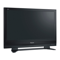
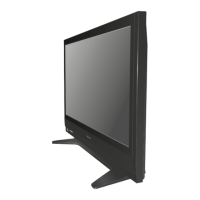
TH-42PE7U
 Loading...