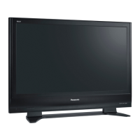
Do you have a question about the Panasonic TH-42PV7M and is the answer not in the manual?
Procedure to measure and verify touch currents on exposed metallic parts.
Procedure to detach the plasma panel section from the cabinet assembly.
Steps for installing the new plasma panel and reassembling the unit.
How to access and perform IIC bus line checks for self-diagnosis.
Chart correlating power LED blinking patterns with defective blocks.
Troubleshooting steps for the 'No Power' indication by the power LED.
Flowchart for diagnosing and resolving 'No Picture' issues.
Step-by-step instructions to enter service mode using remote control commands.
Setup for driver circuits, including item preparation and voltage adjustments.
Adjusting the stand down pulse period after white signal input.
Cautions for PCB removal and quick adjustment steps after replacement.
Procedure for adjusting sub-contrast for AV, RF, and HD systems.
Detailed steps for adjusting white balance for PAL signals using a color analyzer.
Detailed steps for adjusting white balance for HD signals using a color analyzer.
High-level block diagram showing the main functional units of the TV.
Block diagram illustrating the Power Supply (P) board and its connections.
Block diagram showing the input/output signals of the DG-Board, part 1 of 4.
Block diagram showing the input/output signals of the DG-Board, part 2 of 4.
Block diagram showing the input/output signals of the DG-Board, part 3 of 4.
Block diagram showing the input/output signals of the DG-Board, part 4 of 4.
Block diagram of the D-Board, illustrating key components and connections.
Block diagram of the SC-Board, showing signal flow and key components.
Block diagram of the SS-Board, detailing sustain driver functions.
| Screen Size | 42 inches |
|---|---|
| Display Type | Plasma |
| Resolution | 1024 x 768 |
| Response Time | 0.001 ms |
| HDMI Ports | 2 |
| Component Video Inputs | 2 |
| Weight | 29 kg |
| Aspect Ratio | 16:9 |
| HDTV Compatibility | Yes |
| Viewing Angle | 160 degrees |
| Input Ports | Composite, S-Video |
| Contrast Ratio | 10000:1 |


 Loading...