EasyManua.ls Logo

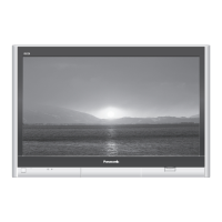
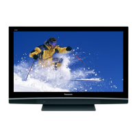
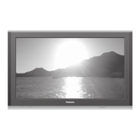
Panasonic TH-42PV60H

Panasonic TH-42PV60H
149 pages
To Next Page IconTo Next Page
Loading...
© 2006 Matsushita Electric Industrial Co., Ltd. All
rights reserved. Unauthorized copying and
distribution is a violation of law.
TH-42PV60A
TH-42PV60H
TH-42PV60M
TH-42PV60MT
GP9DE Chassis
Plasma Television
Specifications
Power Source
A
C 220-240 V, 50 / 60 Hz
Power Consumption
Average use 341 W
Standby condition 0.3 W
Plasma Display panel
Drive method
A
Ctype
Aspect Ratio 16:9
Contrast Ratio Max 10000:1
Visible screen size
(No. of pixels)
106 cmV
920 mm (W) × 518 mm (H) × 1,056 mm (diagonal)
786,432 (1,024 (W) × 768 (H)) [3,072 × 768 dots]
Sound
Speaker 12 cm × 6 cm × 2 pcs, 8 W
Audio Output 20 W (10 W + 10 W ), 10% THD
Headphones M3 (3.5 mm) Jack × 1
PC signals
V
GA, SVGA, XGA
SXGA (compressed)
Horizontal scanning frequency 31 - 69 kHz
V
ertical scanning frequency 59 - 86 Hz
Receiving Systems /
Band name (PV60A)
Receiving Channels (PV60A)
V
HF 0 to 12 PAL B
UHF 21 to 69 PAL G
S’1 to S’3 HYPER TUNER
ORDER NO.ITD0603006CE

Table of Contents

Question and Answer IconNeed help?

Do you have a question about the Panasonic TH-42PV60H and is the answer not in the manual?

Panasonic TH-42PV60H Specifications

General IconGeneral
BrandPanasonic
ModelTH-42PV60H
CategoryPlasma TV
LanguageEnglish

Summary

Specifications

Power Consumption

Specifies average and standby power consumption figures.

Plasma Display Panel

Provides specifications for the plasma display panel, including drive method and aspect ratio.

Safety Warning

Safety Precautions

General Guidelines

General guidelines to follow when servicing the unit, emphasizing safety measures.

Touch-Current Check

Procedure and limits for checking touch currents to prevent shock hazards.

ESD Prevention

Plasma Panel Replacement Method

Remove P-Board

Procedure for removing the Power Supply (P-Board).

Remove PA-Board

Instructions for removing the Audio Amplifier (PA-Board).

Remove DG-Board

Procedure for removing the Digital Signal Processor (DG-Board).

Remove TA-Board

Instructions for removing the Tuner/AV (TA-Board).

Remove H-Board

Procedure for removing the AV Terminal/Switch (H-Board).

Remove HC-Board

Instructions for removing the Jig Connection (HC-Board).

Remove D-Board

Procedure for removing the Format Converter (D-Board).

Remove SU-Board

Instructions for removing the Scan Out (Upper) (SU-Board).

Remove SD-Board

Procedure for removing the Scan Out (Lower) (SD-Board).

Remove SC-Board

Procedure for removing the Scan Drive (SC-Board).

Remove SS-Board

Instructions for removing the Sustain Drive (SS-Board).

Remove C1-Board

Procedure for removing the C1 Data Driver Board.

Remove C2-Board

Instructions for removing the C2 Data Driver Board.

Remove Plasma Panel Section

Procedure for safely separating the plasma panel from the front frame.

Replace Plasma Panel

Final steps for replacing the plasma panel and reassembling the unit.

Self Check Procedures

Power LED Blinking Timing Chart

Chart showing power LED blinking patterns and their corresponding error codes.

No Power Troubleshooting

Troubleshooting steps for identifying the cause of the 'No Power' condition.

No Picture Troubleshooting

Troubleshooting guide for diagnosing and resolving 'No Picture' issues.

Service Mode Functions

Adjustment Procedures

Driver Set-up

Procedure for setting up and adjusting driver circuits, including voltage checks.

Component Adjustments

PAL White Balance Adjustment

Step-by-step guide for adjusting white balance for PAL signals.

HD White Balance Adjustment

Procedure for adjusting white balance for HD signals.

Hotel Mode Configuration

Schematic and Block Diagrams

Parts Location and Mechanical Replacement Parts List

Electrical Replacement Parts List

Electrical Replacement Parts List

Detailed list of electrical replacement parts with part numbers and specifications.
Related product manuals