Do you have a question about the Panasonic TH-42PV8D and is the answer not in the manual?
Guidelines for servicing, including lead dress, protective devices, and leakage current checks.
Procedure and limits for measuring touch currents, including network setup and voltage checks.
Techniques to reduce component damage from static electricity during servicing of ES devices.
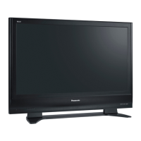
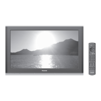
Instructions on how to set the plasma unit on the pedestal stand and remove the rear cover.
Procedure for entering service mode using the remote control and main unit buttons.
Details of adjustment items, values, preset values, and remarks in service mode.
Procedure for exiting service mode by switching off the power.
Steps to access the service tool mode from the service mode.
Explanation of the SOS History indication format and how it is cleared.
How to display and interpret power on time and count, and note on clearing.
Procedure for exiting the service tool mode.
Command sequence to display the hotel mode setup menu.
Procedure for exiting the hotel mode setup menu.
Explanation of items within the hotel mode setup menu.
Procedures for accessing, checking, and exiting IIC bus line diagnostics.
Steps for removing rear cover, P-Board, tuner unit, and GS-Board.
Steps for removing A-Board, SU-Board, SD-Board, SC-Board, SS-Board, and stand brackets.
Steps for removing speakers, K-Board, S-Board, and plasma panel section.
Preparation and procedures for driver setup, including voltage adjustments with a multimeter.
Caution and quick adjustment procedures after replacing PCBs.
Location of adjustment volumes and test points on the panel label and boards.
Important cautions for cable assembly and the overall wire dressing diagram.
Schematic diagram of the A-Board, part 1 of 19, detailing JTAG and IIC connections.
Schematic diagrams for the C1-Board, covering both parts.
Schematic diagrams for the C2-Board, covering both parts.
Schematic diagram of the SC-Board, part 1 of 3, showing power supply and driver circuits.
Schematic diagrams for the SS-Board, covering both parts.
Printed circuit board layouts for the P-Board (foil and component sides).
Printed circuit board layout for the A-Board (foil side), showing component placement.
Printed circuit board layout for the SC-Board (foil side), showing component placement.
Printed circuit board layout for the SS-Board (foil side), showing component placement.
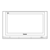
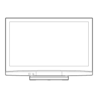
Diagrams illustrating the exploded view of the TV unit and its mechanical components.
Diagrams showing the packing procedure for the TV unit and accessories.
Important safety notice and notes on mechanical replacement parts.
| Screen Size | 42 inches |
|---|---|
| Display Technology | Plasma |
| Resolution | 1024 x 768 |
| Aspect Ratio | 16:9 |
| Contrast Ratio | 10000:1 |
| HDMI Ports | 2 |
| Response Time | 0.001 ms |
| Component Video Inputs | 2 |
| Viewing Angle | 160 degrees |
| Panel Type | Plasma |