Do you have a question about the Panasonic TH-42PV70AZ and is the answer not in the manual?
Details on power source voltage, frequency, and consumption.
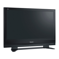
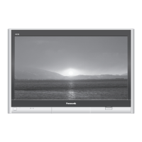
Information on aspect ratio, screen size, and pixel count.
Specifications for speakers, audio output, and PC signal inputs.
Lists VHF, UHF, and CATV channel ranges for various regions.
Specifications for AV, HDMI, and PC input terminals.
General guidelines for conducting repairs and servicing.
Procedure and specifications for performing touch current checks.
Techniques to prevent component damage from electrostatic discharge.
Information and recommendations for using lead-free solder.
Helpful hints and tips for servicing the unit.
Step-by-step instructions for removing major internal components.
Specific instructions for removing various boards like P-Board, PA-Board, etc.
Procedure to safely remove the plasma panel from the cabinet assembly.
Steps for installing and finishing the plasma panel replacement.
Procedure to access and check IIC bus lines for self-diagnosis.
Chart correlating LED blink codes with potential faults.
Diagnostic steps for units that do not power on.
Diagnostic steps for units that display no picture.
Identifying possible PCB defects causing local screen failures.
Instructions on how to enter the service mode menu.
Description of adjustable items and their preset values.
Procedure to access and use the service tool mode for diagnostics.
Items and preparation steps for driver setup.
Procedure for adjusting the initialization pulse.
Cautions and quick adjustment steps after PCB replacement.
Diagrams showing locations of adjustment volumes and test points.
Step-by-step guide for adjusting sub-contrast for AV, RF, and HD systems.
Procedure for adjusting white balance for PAL signals using a color analyzer.
Procedure for adjusting white balance for HD signals using a color analyzer.
Explanation of hotel mode purpose and command to access the setup menu.
Details on various hotel mode settings like input, volume, and remote lock.
Component layout and conductor view of the P-Board.
Component layout and conductor view of the PA-Board.
Component layout and conductor views of the H-Board.
Component layout and conductor views of the DG-Board.
Component layout and conductor views of the D-Board.
Component layout and conductor view of the C1-Board.
Component layout and conductor view of the C2-Board.
Component layout and conductor view of the SC-Board.
Component layout and conductor view of the SU-Board.
Component layout and conductor view of the SD-Board.
Component layout and conductor view of the SS-Board.
Component layout and conductor views of the K and S boards.
Component layout and conductor view of the G-Board.
Important notes on symbols, test points, and measurements.
Overall block diagram illustrating system connectivity and signal flow.
Block diagram of the P-Board power supply circuit.
Detailed schematic diagrams of the P-Board, presented in six parts.
Block diagram and schematic diagram for the PA-Board DC-DC converter.
Block diagrams for the H-Board, illustrating AV, PC, and tuner connections.
Detailed schematic diagrams of the H-Board, presented in five parts.
Block diagrams for the DG-Board, covering HDMI, USB, and signal processing.
Detailed schematic diagrams of the DG-Board, presented in nine parts.
Block diagram and detailed schematic diagrams for the D-Board.
Block diagrams illustrating the functionality of C1 and C2 data driver boards.
Detailed schematic diagrams of the C1-Board, presented in two parts.
Detailed schematic diagrams of the C2-Board, presented in two parts.
Block diagram and detailed schematic diagrams for the SC-Board.
Block diagrams illustrating the functionality of SU and SD scan driver boards.
Detailed schematic diagrams of the SU-Board, presented in two parts.
Detailed schematic diagrams of the SD-Board, presented in two parts.
Block diagram and detailed schematic diagrams for the SS-Board.
Schematic diagrams for the G-Board and K-Board.
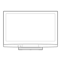
Visual exploded views of the TV components.
Exploded views illustrating the packing of the television.
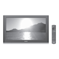
List and illustrations of included accessories.
Important notes and abbreviations for the replacement parts list.
Detailed list of mechanical parts with part numbers and descriptions.
Detailed list of electrical components with part numbers and descriptions.
| Screen Size | 42 inches |
|---|---|
| Panel Type | Plasma |
| Contrast Ratio | 10000:1 |
| HDMI Ports | 2 |
| HDTV Compatibility | Yes |
| Aspect Ratio | 16:9 |
| Input Ports | Component, Composite, VGA |
| Resolution | 1024 x 768 pixels |
| Response Time | 0.001 seconds |