EasyManua.ls Logo

Panasonic TH-42PV7MR - User Manual

Panasonic TH-42PV7MR
135 pages
To Next Page IconTo Next Page
Loading...
© 2007 Matsushita Electric Industrial Co., Ltd. All
rights reserved. Unauthorized copying and
distribution is a violation of law.
GPH10DA Chassis
Plasma Television
Specifications
Powe
r
Source
A
C 220-240 V, 50
/
60 Hz
Powe
r
Consumption
Aver
a
ge use 350 W
Standby condition 0.7 W
Displa
y
panel
Aspect Ratio 16 : 9
V
isible screen size 106 cm (diagonal)
922 mm (W) × 518 mm (H)
Numbe
r
o
f
pixels 786,432 (1,024 (W) × 768 (H)) [3,072 × 768 dots]
Sound
Speake
120 mm × 60 mm × 2 pcs, 8 ohm
Audio Output 20 W [10 W + 10 W] (10 % THD)
PC signals VGA, SVGA, XGA
SXGA ...... (compressed)
Horizontal scanning frequency 31 - 69 kHz
Vertical scanning frequency 59 - 86 Hz
Receiving Systems/Band name PAL B/G
(PX7A only) Reception of Off ai
r
broadcasts
DVB-T
7 MHz VHF
/
UHF (Australia) free-to-ai
r
TV broadcast reception
PAL 60 Hz
Playback of NTSC tape from some PAL Video recorders (VCR)
M.NTSC
Playback from M. NTSC Video recorders (VCR)
NTSC
Playback from NTSC Video recorders (VCR)
ORDER NO.PPDS070638CE

Table of Contents

Question and Answer IconNeed help?

Do you have a question about the Panasonic TH-42PV7MR and is the answer not in the manual?

Panasonic TH-42PV7MR Specifications

General IconGeneral
BrandPanasonic
ModelTH-42PV7MR
CategoryPlasma TV
LanguageEnglish

Summary

Product Specifications

Power, Display, and Sound Specs

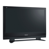
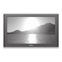
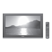
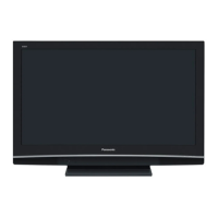
Details on power, display panel, and sound system specifications.

Receiving Systems and Channels

Supported broadcast reception systems and channel frequency bands.

Input;Output and Operating Conditions

Connection terminals, signal inputs, and operating environment requirements.

Safety, ESD, and Solder Information

General Safety and ESD Prevention

Guidelines for safe servicing and electrostatic discharge prevention.

Touch-Current Check

Procedure for checking touch-current leakage.

Lead Free Solder

Information on lead-free solder composition and handling.

Service Procedures and Notes

Service Hints and Panel Replacement

Hints for servicing, rear cover removal, and plasma panel replacement steps.

Caution Statements and Lead Wiring

Servicing cautions and diagrams of internal lead wiring.

Self-check, Service Modes, and Adjustments

Self-check Functions

Procedures for unit self-checks and error code interpretation.

Service Mode Access and Operation

Methods to enter service mode, use tools, and perform adjustments.

Adjustment Procedures

Detailed steps for driver setup, pulse adjustment, and white balance calibration.

Board Views and Parts Lists

Conductor Views

Layouts of components and traces on main circuit boards.

Block and Schematic Diagrams

High-level functional block diagrams and detailed circuit schematics.

Exploded Views and Parts Lists

Visual guide to parts, packing, accessories, and replacement part numbers.

Related product manuals