EasyManua.ls Logo

Panasonic TH-42PV7AZ - User Manual

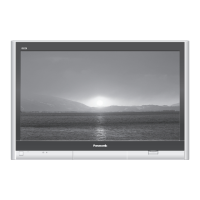
Panasonic TH-42PV7AZ
135 pages
To Next Page IconTo Next Page
Loading...
© 2007 Matsushita Electric Industrial Co., Ltd. All
rights reserved. Unauthorized copying and
distribution is a violation of law.
GPH10DA Chassis
Plasma Television
Specifications
Powe
r
Source
A
C 220-240 V, 50
/
60 Hz
Powe
r
Consumption
Aver
a
ge use 350 W
Standby condition 0.7 W
Displa
y
panel
Aspect Ratio 16 : 9
V
isible screen size 106 cm (diagonal)
922 mm (W) × 518 mm (H)
Numbe
r
o
f
pixels 786,432 (1,024 (W) × 768 (H)) [3,072 × 768 dots]
Sound
Speake
120 mm × 60 mm × 2 pcs, 8 ohm
Audio Output 20 W [10 W + 10 W] (10 % THD)
PC signals VGA, SVGA, XGA
SXGA ...... (compressed)
Horizontal scanning frequency 31 - 69 kHz
Vertical scanning frequency 59 - 86 Hz
Receiving Systems/Band name PAL B/G
(PX7A only) Reception of Off ai
r
broadcasts
DVB-T
7 MHz VHF
/
UHF (Australia) free-to-ai
r
TV broadcast reception
PAL 60 Hz
Playback of NTSC tape from some PAL Video recorders (VCR)
M.NTSC
Playback from M. NTSC Video recorders (VCR)
NTSC
Playback from NTSC Video recorders (VCR)
ORDER NO.PPDS070638CE

Table of Contents

Question and Answer IconNeed help?

Do you have a question about the Panasonic TH-42PV7AZ and is the answer not in the manual?

Panasonic TH-42PV7AZ Specifications

General IconGeneral
BrandPanasonic
ModelTH-42PV7AZ
CategoryPlasma TV
LanguageEnglish

Summary

Specifications

Safety Precautions

General Guidelines for Repairs

Provides rules and guidelines for conducting safe equipment repairs and servicing.

Touch-Current Check Procedure

Describes the method for checking touch currents to prevent shock hazards.

Prevention of Electrostatic Discharge (ESD)

Plasma Panel Replacement Method

Remove Rear Cover and Boards

Details the process of removing the rear cover, tuner, and main boards.

Self-check Function

Check of IIC Bus Lines

Details accessing and checking the IIC bus lines for self-check.

Power LED Blinking Timing Chart

Provides a chart correlating LED blinks to potential unit abnormalities.

No Power Troubleshooting

Troubleshooting steps for power indication issues.

No Picture Troubleshooting

Troubleshooting steps for issues where no picture is displayed.

Local Screen Failure Analysis

Discusses local screen failures and identifies potential defective PCBs.

Service Mode Operations

Entering Service Mode

Explains the key sequence required to access the service mode.

Adjustment Procedures

Driver Set-up and Adjustments

Covers driver setup, item preparation, and voltage adjustments.

Initialization Pulse Adjustment

Describes the procedure for initializing the pulse signal.

Sub-Contrast Adjustment

Procedure for adjusting sub-contrast across different signal sources.

White Balance Adjustment (PAL;HD)

Procedure for adjusting white balance for PAL and HD signals.

Schematic and Block Diagrams

Replacement Parts List Notes

Important Safety Notice

Safety notice regarding critical components.

Related product manuals