Home
Panasonic
Monitor
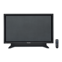
TH-42PWD8WK
Panasonic TH-42PWD8WK - User Manual
398 pages
Manual
Specs
Ask a question
Save Page as PDF
To Next Page
To Next Page
Loading...
O
RD
E
R
N
O. I
T
D
0509049
AE
W
i
de
P
l
asma
D
i
sp
l
ay
TH-
42
PWD
8
WK / TH-
42
PWD
8
WS / TH-
37
PWD
8
WK / TH-
37
PWD
8
WS
G
P8
D
C
hass
is
P
l
ease
f
il
e
and
use
th
i
s
manua
l
together
wi
th
the
serv
i
ce
manua
l
for
Mode
l
N
o
.
T
H
-42PW
D
8
BK
, O
RD
E
R
N
O. I
T
D
0506035
C
E.
2005
Matsush
i
ta
E
l
ectr
i
c
I
ndustr
i
a
l
C
o
.,
Ltd
.
A
ll
r
i
ghts
reserved
.
U
nauthor
i
zed
cop
y
i
ng
and
d
i
str
i
but
i
on
i
s
a
v
i
o
l
at
i
on
of
l
a
w.
1. Difference point
1
.
1
.
T
H
-42PW
D
8W
K
/
WS
1
2
Table of Contents
Main Page
Specifications
5
Applicable Signals
7
Safety Precautions
9
General Guidelines
9
Leakage Current Cold Check
9
Leakage Current Hot Check
10
Prevention of Electrostatic Discharge (Esd) to Electrostatically Sensitive (Es) Devices
10
About Lead Free Solder (Pbf)
11
PCB Structure Sheet of GP8D Chassis
13
Service Hint
14
Removal of the Slot Block
16
Removal of the J-Board
17
Removal of the HX-Board
18
Removal of the P-Board
20
Removal of the D-Board
21
Removal of the AC-Inlet
22
Removal of the H3-Board
23
Removal of the S1-Board
25
Removal of the SU-Board
26
Removal of the SD-Board
28
Removal of the SC-Board
32
Removal of the SS-Board
33
Removal of the C1-Board
34
Removal of the C2-Board
35
Removal of the Front Frame (Glass)
36
Removal of the V1-Board and the V2-Board
39
Removal of Stand Brackets
39
Replacement of the Plasma Panel
40
Location of Lead Wiring
40
Wiring for 37 Inch Model
40
Wiring for 42 Inch Model
42
Adjustment Procedure
44
Driver Set-Up
44
Item / Preparation
44
Initialization Pulse Adjust
45
Printed Circuit Board) Exchange
46
Quick Adjustment after P.C.B. Exchange
47
Adjustment Volume Location
47
Test Point Location
48
Service Mode
49
IIC Mode
50
IIC Mode Structure (Following Items Value Is Sample Data.)
54
PC/RGB Panel White Balance
56
Troubleshooting Guide
56
Self Check
56
Display Indication
56
Power LED Blinking Timing Chart
57
Local Screen Failure
59
Option Setting
60
Circuit Board Layout
61
Block and Schematic Diagrams
65
Parts Location
76
Packing Exploded Views
77
Mechanical Replacement Parts List
77
Replacement Parts List Notes
81
Electrical Replacement Parts List (37Inch)
82
Electrical Replacement Parts List (42Inch)
137
Schematic Diagram for Printing with A4
189
Main Block Diagram
193
P-Board Block Diagram
195
P-Board (1 of 6) Schematic Diagram
197
P-Board (2 of 6) Schematic Diagram
199
P-Board (3 of 6) Schematic Diagram
201
P-Board (4 of 6) Schematic Diagram
203
P-Board (5 of 6) Schematic Diagram
205
P-Board (6 of 6) Schematic Diagram
207
HA-Board Block and Schematic Diagram
209
HB-Board Block Diagram
211
HB-Board (1 of 2) Schematic Diagram
213
HB-Board (2 of 2) Schematic Diagram
215
HX-Board Block Diagram
217
HX-Board Schematic Diagram
219
J-Board (1 of 2) and H3-Board Block Diagram
223
J-Board (2 of 2) Block Diagram
225
J-Board (2 of 4) Schematic Diagram (37 Inch)
229
J-Board (3 of 4) Schematic Diagram (37 Inch)
231
J-Board (4 of 4) Schematic Diagram (37 Inch)
233
J-Board (2 of 4) Schematic Diagram (42 Inch)
237
D-Board Block Diagram
243
D-Board (1 of 12) Schematic Diagram
245
D-Board (2 of 12) Schematic Diagram
247
D-Board (3 of 12) Schematic Diagram
249
D-Board (4 of 12) Schematic Diagram
251
D-Board (5 of 12) Schematic Diagram
253
D-Board (6 of 12) Schematic Diagram
255
D-Board (7 of 12) Schematic Diagram
257
D-Board (8 of 12) Schematic Diagram
259
D-Board (9 of 12) Schematic Diagram
261
D-Board (10 of 12) Schematic Diagram
263
D-Board (11 of 12) Schematic Diagram
265
D-Board (12 of 12) Schematic Diagram
267
C1 and C2-Board Block Diagram
269
C1-Board (1 of 2) Schematic Diagram (37 Inch)
271
C1-Board (2 of 2) Schematic Diagram (37 Inch)
273
C1-Board (1 of 2) Schematic Diagram (42 Inch)
275
C1-Board (2 of 2) Schematic Diagram (42 Inch)
277
C2-Board (1 of 2) Schematic Diagram (37 Inch)
279
C2-Board (2 of 2) Schematic Diagram (37 Inch)
281
C2-Board (1 of 2) Schematic Diagram (42 Inch)
283
C2-Board (2 of 2) Schematic Diagram (42 Inch)
285
SC-Board Block Diagram
287
SC-Board (1 of 2) Schematic Diagram
289
SC-Board (2 of 2) Schematic Diagram
291
SU-Board Block Diagram
293
SU-Board Schematic Diagram (37 Inch)
295
SU-Board Schematic Diagram (42 Inch)
297
SD-Board Block Diagram
299
SD-Board Schematic Diagram (37 Inch)
301
SD-Board Schematic Diagram (42 Inch)
303
SS-Board Block Diagram
305
SS-Board Schematic Diagram
307
Press to Confirm
313
Need help?
Do you have a question about the Panasonic TH-42PWD8WK and is the answer not in the manual?
Ask a question
Panasonic TH-42PWD8WK Specifications
Print Specification
General
Screen Size
42 inches
Panel Type
Plasma
Brightness
1000 cd/m²
Contrast Ratio
3000:1
Viewing Angle
160 degrees
Aspect Ratio
16:9
Input Ports
Composite
Related product manuals
Panasonic TH-42PWD8WS
398 pages
Panasonic TH 42PWD4
44 pages
Panasonic TH-42PWD6
40 pages
Panasonic TH-42PWD5
44 pages
Panasonic Viera TH-42PWD4
44 pages
Panasonic TH-42PW3
36 pages
Panasonic TH-42PW5
44 pages
Panasonic TH-42PW6
36 pages
Panasonic TH-42PW4
44 pages
Panasonic TH-42PHD5
40 pages
Panasonic TH-42PS9ES
48 pages
Panasonic TH-42PH11GK
156 pages