Home
Panasonic
LCD TV
TH-L32X20Z
Panasonic TH-L32X20Z
81 pages
Manual
To Next Page
To Next Page
To Previous Page
To Previous Page
Loading...
TH-L32X20Z
22
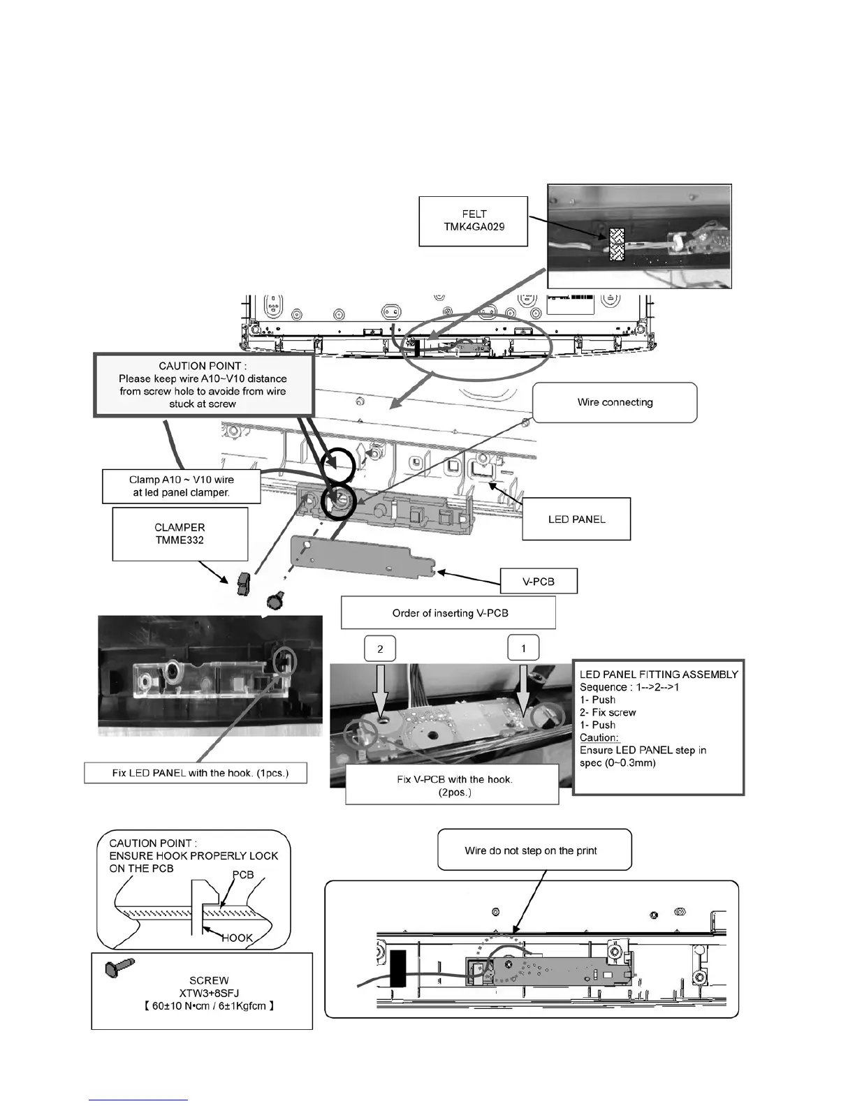
7.9.
LED Panel Inst
allation & Fitting
1.
Fix LED P
ANEL on CAB
INET
.
2.
Insert an A10-V10 le
ad connector in V
-Print.
3.
Put V
-PCB on LED P
A
NEL.
4.
Fix LED P
ANEL a
ss’y with SCREW
.
5.
Insert the CLAMPER and stick FEL
T at V10 wire.
21
23
Table of Contents
Main Page
Default Chapter
1
Table of Contents
1
1 Safety Precautions
3
General Guidelines
3
Leakage Current Cold Check
3
Leakage Current Hot Check (See Figure 1.)
3
2 Warning
4
Prevention of Electrostatic Discharge (ESD) to Electrostatically Sensitive (ES) Devices
4
About Lead Free Solder (Pbf)
5
3 Service Navigation
6
Service Hint
6
Applicable Signals
7
4 Specifications
8
5 Service Mode
9
How to Enter into Service Mode
9
Contents of Adjustment Mode
9
How to Exit
9
Srv-Tool
10
How to Access
10
Display of SOS History
10
Power on Time/Count
10
Exit
10
Service Mode Adjustment
11
Self Check Mode
11
Hotel Mode Adjustment
11
Hotel Mode
11
6 Troubleshooting Guide
12
Check of the IIC Bus Lines
12
How to Access
12
Exit
12
Screen Display
12
Check Point
12
Power LED Blinking Timing Chart
13
No Power
13
7 Disassembly and Assembly Instructions
14
AC Cord Dressing
14
AC Cord Installation
15
VESA Rail Installation
16
VESA Metal Assembly
17
Control Panel Assembly
18
Side AV Assembly Installation
19
SP Installation
20
LCD Panel Installation
21
LED Panel Installation & Fitting
22
LCD Mounting Installation
23
LCD Mounting Installation
24
LCD Mounting Installation
25
Metal Bracket Installation
26
EMI Spec (LVDS) (1)
27
EMI Spec (LVDS) (2)
28
PCB and Clamper Assembly
29
PB MTG Installation
30
Pedestal Assembly
31
Pedestal Assembly
33
Rear Cover
33
Stand MTG Assembly
34
8 Measurements and Adjustments
35
Voltage Chart of A-Board
35
Voltage Chart of P-Board
35
Power Supply for Sub Print Line
35
Picture Level Adjustment (RF)
36
Picture Level Adjustment (VIDEO)
36
Picture Level Adjustment (YUV)
36
9 Block Diagram
37
Main Block Diagram
37
10 Wiring Connection Diagram
38
11 Schematic Diagram
39
Schematic Diagram Notes
39
A-Board (1/17) Schematic Diagram
40
A-Board (2/17) Schematic Diagram
41
A-Board (3/17) Schematic Diagram
42
A-Board (4/17) Schematic Diagram
43
A-Board (5/17) Schematic Diagram
44
A-Board (6/17) Schematic Diagram
45
A-Board (7/17) Schematic Diagram
46
A-Board (8/17) Schematic Diagram
47
A-Board (9/17) Schematic Diagram
48
A-Board (10/17) Schematic Diagram
49
A-Board (11/17) Schematic Diagram
50
A-Board (12/17) Schematic Diagram
51
A-Board (13/17) Schematic Diagram
52
A-Board (14/17) Schematic Diagram
53
A-Board (15/17) Schematic Diagram
54
A-Board (16/17) Schematic Diagram
55
A-Board (17/17) Schematic Diagram
56
K-Board Schematic Diagram
57
P-Board Schematic Diagram
58
V-Board Schematic Diagram
59
12 Printed Circuit Board
60
A-Board
60
A-Board
61
K-Board
62
V-Board
62
P-Board
63
P-Board
65
Related product manuals
Panasonic TH-L32X20A
56 pages
Panasonic TH-L32X20S
82 pages
Panasonic Viera TH-L32X20Z
56 pages
Panasonic Viera TH-L32X20A
56 pages
Panasonic VIERA TH-L32X25A
64 pages
Panasonic TH-L32X10A
77 pages
Panasonic TH-L32X10H
148 pages
Panasonic TH-L32X50D
65 pages
Panasonic TH-L32X50Z
84 pages
Panasonic Viera TH-L32X15M
48 pages
Panasonic Viera TH-L32X10K
52 pages
Panasonic VIERA TH-L32X30A
76 pages