TH-L32X20Z
36
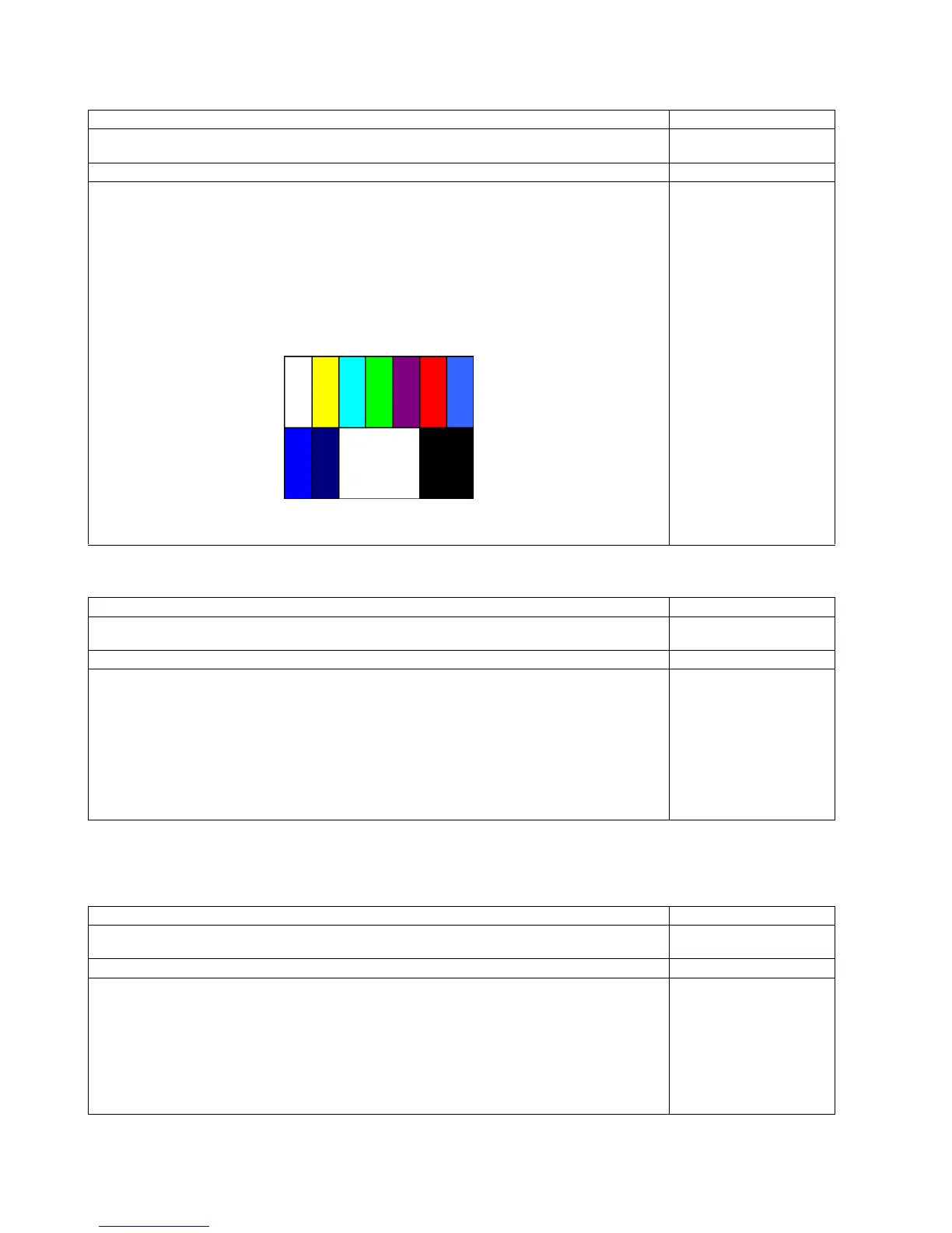
8.4. Picture level adjustment (RF)
8.5. Picture level adjustment (VIDEO)
8.6. Picture level adjustment (YUV)
Instrument Name Remarks
1. REMOTE TRANSMITTER
2. Ex. Signal (Sprit color bar)
Adjustment or Inspection Procedure Remarks
<procedure>
1. Receive the Sprit color bar.
(Screen mode: ZOOM or FULL Picture mode: DYNAMIC AI: OFF AI Picture: OFF)
*BACK LIGHT +30
<Inspection>
1. Enter Service mode, and select MAIN_ADJ PICTURE.
Volume UP/DOWN key makes GAIN displayed under PICTURE to set.
Pushing the remote controller [OK] key for about 3 seconds, GAIN is suited
to the adjustment value automatically.
(The Sprit Color Bar Pattern)
Instrument Name Remarks
1. REMOTE TRANSMITTER
2. Video signal generator (100% Color bar)
Adjustment or Inspection Procedure Remarks
<procedure>
1. Receive 100% Color bar.
(ASPECT: ZOOM or FULL, Picture mode: VIVID, AI Picture: OFF)
* BACK LIGHT MAX VALUE
<Inspection>
1. Enter Service mode, and select ADJUST CONTRAST.
Volume UP/DOWN key makes GAIN value displayed on the right of CONTRAST to set.
Pushing the remote controller [OK] key for about 3 seconds, GAIN is suited to the adjustment value
automatically.
Instrument Name Remarks
1. REMOTE TRANSMITTER
2. Component Video signal generator (100% Color bar 1080i)
Adjustment or Inspection Procedure Remarks
<procedure>
1. Receive 100% Color bar.
(ASPECT: ZOOM or FULL, Picture mode: VIVID, AI Picture: OFF)
* BACK LIGHT MAX VALUE
<Inspection>
1. Enter Service mode, and select ADJUST CONTRAST.
Volume UP/DOWN key makes GAIN value displayed on the right of CONTRAST to set.
Pushing the remote controller [OK] key for about 3 seconds, GAIN is suited to the adjustment value
automatically.
 Loading...