EasyManua.ls Logo

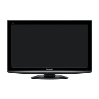
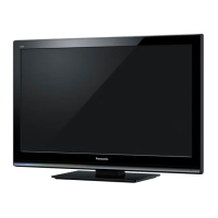
Panasonic TH-L32X10A

Panasonic TH-L32X10A
77 pages
To Next Page IconTo Next Page
Loading...
© Panasonic Corporation 2009. Unauthorized
copying and distribution is a violation of law.
TH-L32X10A
LH88 Chassis
LCD TV
Specifications
Power Source
AC 220-240V, 50/60 Hz
Power Consumption
Power rating:114W
Normal(Home) mode:91W
Standby condition:0.4W
LCD
80cm
Wide XGA (1366 × 768 pixels) 16:9 aspect ratio LCD panel.
Screen Size
698mm(W) × 393mm(H)
Sound
Speaker
160mm × 42mm× 2pcs,8
Audio Output
20W(10W+10W)10% THD
Headphones
M3 (3.5 mm)stereo mini Jack × 1
PC signals
VGA, SVGA, XGA
SXGA ...........(com pressed)
Horizontal scanning frequency 31 - 69 kHz
Vertical scanning frequency 59 - 86 Hz
Receiving System/Band name
PAL B/G
Reception of Off air broadcasts
DVB-T
7MHz VHF/UHF(Australia)free-to-air TV broadcast reception
PAL 60Hz
Playback of NTSC tape from some PAL Video recorders(VCR)
M.NTSC
Playback from M.NTSC Video recorders(VCR)
NTSC
Playback from NTSC Video recorders(VCR)
Aerial-Rear
VHF/UHF
Operating Conditions
Temperature : 0°C - 35°C
Humidity : 20 % - 80 % RH (non-condensing)
Connection Terminals
ORDER NO. SMT0902002CE

Table of Contents

Question and Answer IconNeed help?

Do you have a question about the Panasonic TH-L32X10A and is the answer not in the manual?

Panasonic TH-L32X10A Specifications

General IconGeneral
Screen Size32 inches
Resolution1366 x 768
Display TypeLCD
Brightness500 cd/m²
HDMI Ports3
USB Ports1
Aspect Ratio16:9
Viewing Angle178°
HDTV Compatibility720p

Summary

Specifications

WARNING

Safety Precautions

General Servicing Guidelines

Guidelines for safe servicing and testing procedures.

Leakage Current Checks

Procedures for performing cold and hot leakage current tests.

ESD Prevention Measures

IMPORTANT SAFETY NOTICE

Self-Check Functionality

Performing Self-Check

Steps to perform self-check and its consequences.

Power LED Blinking Codes

Chassis Board Layout

Pre-Servicing Checks

Maintenance Disassembly Procedures

Board Disassembly

Internal Component Removal

Service Mode Operations

Entering Service Mode

Key combinations to access the service menu.

Service Mode Navigation Keys

Navigation controls within the service mode.

Adjustment Parameters

Details on adjustable parameters and their values.

SRV-TOOL Utility

Accessing SRV-TOOL

Steps to enter the SRV-TOOL interface.

Option Code Description

OPTION Setting Procedure

Hotel Mode Configuration

Accessing Hotel Mode Menu

Key sequence to enter the hotel mode setup menu.

Hotel Mode Menu Settings

Detailed description of each setting within the hotel mode.

Adjustment Methods

P-board Voltage Test Points

Test points and voltage specifications for the P-board.

A-board Voltage Test Points

Test points and voltage specifications for the A-board.

Schematic Diagrams

Schematic Diagram Notes

Explains symbols, abbreviations, and safety notes for diagrams.

P-Board Schematics

P-Board schematic diagrams (Parts 1-3).

A-Board Schematics

A-Board schematic diagrams (Parts 1-24).

K-Board Schematic

Schematic diagram for the K-Board.

Mechanical Replacement Parts List

Electrical Replacement Parts List

Related product manuals