1 Safety Precautions 4
1.1. General Guidelines
4
2 Prevention of Electrostatic Discharge (ESD) to
Electrostatically Sensitive (ES) Devices
4
3 About lead free solder (PbF)
5
4 Input signal that can be displayed
6
5 Self-check function
7
5.1. How to access
7
5.2. Screen display
7
6 Chassis Board Layout
8
7 Disassembly for Service
9
7.1. Pedestal ass’y
9
7.2. Rear cover
9
7.3. Rear Support MTG (Left and right)
9
7.4. AC cord
10
7.5. Tuner Cover Ass’y
11
7.6. Power Button Bracket Ass’y
11
7.7. Control Panel Ass’y
12
7.8. P-Board
12
7.9. A-Board
13
7.10. AP-Board
13
7.11. G-Board
13
7.12. V-Board and Led Panel
15
7.13. Speaker
16
7.14. Main Chassis Ass’y
16
7.15. LCD Panel
17
8 Location of Lead Wiring
18
9 EMI Processing
20
10 Service Mode Function
22
10.1. How to enter SERVICE 1
22
10.2. How to enter SERVICE 2
22
10.3. Option Description
24
10.4. Option Code Setting
25
11 Adjustment
26
11.1. Voltage chart of A-Board
26
11.2. Voltage chart of AP-Board
26
11.3. Voltage chart of P-Board
26
11.4. DVCO adjustment
27
12 Conductor Views
29
12.1. P-Board
29
12.2. AP-Board
31
12.3. A-Board
33
12.4. V and G-Board
39
13 Block and Schematic Diagram
41
13.1. Schematic Diagram Notes
41
13.2. Main Block Diagram
42
13.3. P.C.B. Block Diagram
43
13.4. Power Block Diagram
44
13.5. Signal Block Diagram
45
13.6. Interconnection Schematic Diagram
46
13.7. P-Board Schematic Diagram (TX-26/32LX70A/X and TX-
26/32LE7X)
47
13.8. P-Board Schematic Diagram (TX-26/32LX70Y and TX-
26/32LE7Y)
48
13.9. AP-Board Schematic Diagram
49
13.10. A-Board (1 of 5) Schematic Diagram
50
13.11. A-Board (2 of 5) Schematic Diagram
51
13.12. A-Board (3 of 5) Schematic Diagram
52
13.13. A-Board (4 of 5) Schematic Diagram
53
13.14. A-Board (5 of 5) Schematic Diagram
54
13.15. G-Board Schematic Diagram
55
13.16. V-Board Schematic Diagram
56
14 Parts Location
57
15 Packing Exploded View
59
16 Mechanical Replacement Parts List
61
17 Electrical Replacement Parts List
66
17.1. Replacement Parts List Notes
66
17.2. Electrical Replacement Parts List
67
657mm × 473mm × 128mm (TX-26LE7X/Y) 791mm × 563mm × 128mm (TX-32LE7X/Y)
Weight
13.5 kg Net (TX-26LX70X/A/Y) 17.5 kg Net (TX-32LX70X/A/Y)
14.0 kg Net (TX-26LE7X/Y) 18.0 kg Net (TX-32LE7X/Y)
Note:
Design and specifications are subject to change without notice. Weight and Dimensions shown are approximate.
CONTENTS
Page Page
3
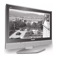
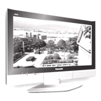
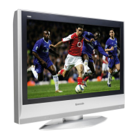
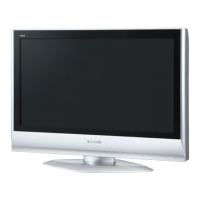
TX-32LX70X / TX-32LX70A / TX-32LX70Y / TX-32LE7X / TX-32LE7Y / TX-26LX70X / TX-26LX70A / TX-26LX70Y / TX-26LE7X / TX-26LE7Y
 Loading...