- 8 -
Service Hints
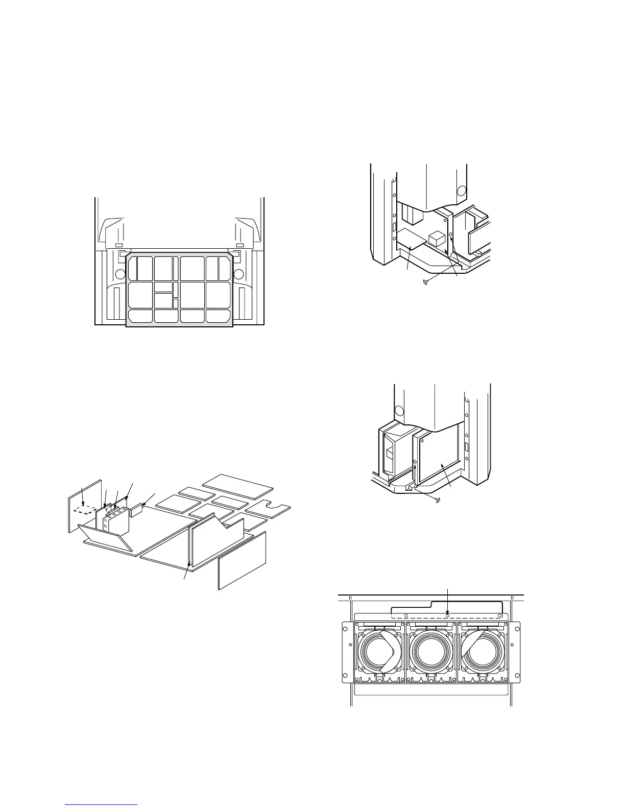
Service position for Main chassis
1. Remove the Rear Cover (Bottom) by removing
(19) screws around its perimeter.
2. Remove lead wires and bundles from holders as
necessary.
3. Pull out main chassis and stand it.
Service Position for D/F/W/T/CF/DC
B2-Board
1. Remove the each circuit board from A or E-Board.
2. Connect extension cables between individual cir-
cuit board and A or E-Board.
Note: Extension cable kit is supplied as service fix-
tures and tools. ( Part No. TZS709010 )
Service Position for CP, DC-Board
1. Remove the Rear Cover (Bottom) by removing
(19) screws around its perimeter.
2. Remove (1) screws secured the CP and DC
Board.
3. Pull out the CP and DC Board.
Service Position for P-Board
1. Remove the Rear Cover (Bottom) by removing
(19) screws around its perimeter.
2. Remove (1) screws secured the P Board.
3. Pull out the P Board.
Service Position for G-Board
1. Remove the Top Cabinet Ass’y.
2. Remove G-Board by removing (3) screws.
AE
Main chasisis
A
E
D
CF
W
F
T
DC
B2
CP-Board
DC-Board
P-Board
G-Board
(3) Screws