EasyManua.ls Logo

Panasonic tx-lr32c10 - User Manual

Panasonic tx-lr32c10
121 pages
To Next Page IconTo Next Page
Loading...
© Panasonic Corporation 2009. Unauthorized
copying and distribution is a violation of law
ORDER NO. MTV0901829CE
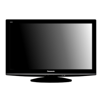
LCD TV
Model No. TX-LR32C10
Chassis: KM02
Destination: CIS
Specifications
Power Source AC SINGLE 220 - 240V, 50/60 Hz
Power Consumption
Average use 121 W
Standby condition 0.7 W
Display panel
Aspect Ratio 16:9
Visible screen size 80 cm (diagonal)
698 mm (W) × 392 mm (H)
Number of pixels 1,049,088 (1,366 (W) × 768 (H))
Sound
Speaker Full range × 2 pcs, 8 Ω
Audio Output 20 W (10 W + 10 W), 10% THD
PC Signals VGA, SVGA, XGA
SXGA ...... (compressed)
Horizontal scanning frequency 31 - 69 kHz
Vertical scanning frequency 59 - 86 Hz
Receiving Systems / Band name 17 SYSTEMS FUNCTIONS
1 PAL B, G, H
Reception of broadcast transmissions and
playback from video cassette tape recorders.
2 PAL I
3 PAL D, K
4 SECAM B, G
5 SECAM D, K
6 SECAM K1
7 NTSC M (NTSC 3.58 / 4.5MHZ)
8 NTSC 4.43 / 5.5 MHz
Playback from special VCR’s or DVD.
9 NTSC 4.43 / 6.0 MHz
10 NTSC 4.43 / 6.5 MHz
11 NTSC 3.58 / 5.5 MHz
12 NTSC 3.58 / 6.0 MHz
13 NTSC 3.58 / 6.5 MHz
14 SECAM I

Table of Contents

Question and Answer IconNeed help?

Do you have a question about the Panasonic tx-lr32c10 and is the answer not in the manual?

Panasonic tx-lr32c10 Specifications

General IconGeneral
Display TypeLCD
Resolution1366 x 768
Aspect Ratio16:9
VGA Port1
Component Video Input1
Composite Video Input1
RF Input1
Headphone Output1
Power Consumption110 W
Standby Power Consumption0.3 W
Screen Size32 inches
Viewing Angle178°

Summary

TV Specifications

Power Source Details

Details on the AC power input requirements and frequency.

Power Consumption Figures

Information on the average and standby power usage.

Display Panel Characteristics

Specifications for aspect ratio, screen size, and pixel count.

Important Safety Precautions

General Servicing Guidelines

Key safety instructions for performing service and repairs.

Touch-Current Measurement Procedure

Procedure for checking leakage current on exposed metallic parts.

Electro Static Discharge (ESD) Prevention

ESD Handling Best Practices

Techniques to prevent component damage from static electricity.

Power LED Blinking Codes

Interpreting LED Flash Patterns

Guide to identifying defective blocks based on LED blinking times.

Disassembly and Assembly Procedures

Service Mode Operations

Technical Measurements and Adjustments

Schematic Diagram Sections

Schematic Diagram Notes

Explanation of symbols, units, and measurement conventions used in schematics.

Parts Identification and Lists

Electrical Replacement Parts List

Comprehensive list of electrical components for service.

Related product manuals