23
7.2. Power LED Blinking timing chart
1. Subject
Information of LED Flashing timing chart.
2. Contents
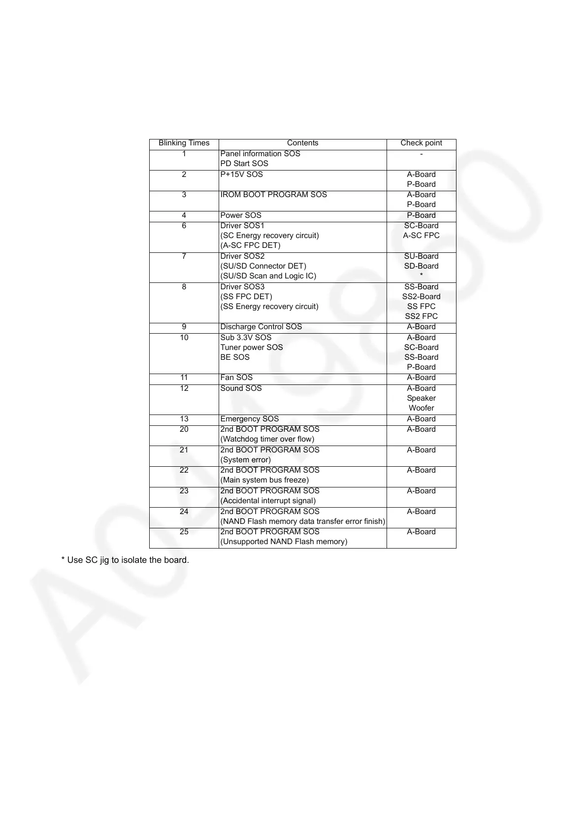
When an abnormality has occurred the unit, the protection circuit operates and reset to the stand by mode. At this time, the
defective block can be identified by the number of blinks of the Power LED on the front panel of the unit.
* Use SC jig to isolate the board.
Blinking Times Contents Check point
1 Panel information SOS
PD Start SOS
-
2 P+15V SOS A-Board
P-Board
3 IROM BOOT PROGRAM SOS A-Board
P-Board
4 Power SOS P-Board
6 Driver SOS1
(SC Energy recovery circuit)
(A-SC FPC DET)
SC-Board
A-SC FPC
7 Driver SOS2
(SU/SD Connector DET)
(SU/SD Scan and Logic IC)
SU-Board
SD-Board
*
8 Driver SOS3
(SS FPC DET)
(SS Energy recovery circuit)
SS-Board
SS2-Board
SS FPC
SS2 FPC
9 Discharge Control SOS A-Board
10 Sub 3.3V SOS
Tuner power SOS
BE SOS
A-Board
SC-Board
SS-Board
P-Board
11 Fan SOS A-Board
12 Sound SOS A-Board
Speaker
Woofer
13 Emergency SOS A-Board
20 2nd BOOT PROGRAM SOS
(Watchdog timer over flow)
A-Board
21 2nd BOOT PROGRAM SOS
(System error)
A-Board
22 2nd BOOT PROGRAM SOS
(Main system bus freeze)
A-Board
23 2nd BOOT PROGRAM SOS
(Accidental interrupt signal)
A-Board
24 2nd BOOT PROGRAM SOS
(NAND Flash memory data transfer error finish)
A-Board
25 2nd BOOT PROGRAM SOS
(Unsupported NAND Flash memory)
A-Board