EasyManua.ls Logo

Panasonic TX-PR42G10 - User Manual

Panasonic TX-PR42G10
140 pages
Print Icon
To Next Page IconTo Next Page
Loading...
ORDER NO.PCZ0903029CE
Plasma Television
Model No. TX-PR42G10
GPF12DE Chassis
A WARNING
This service information is designed for experienced repair technicians only and is not designed for use by the general public.
It does not contain warnings or cautions to advise non-technical individuals of potential dangers in attempting to service a product.
Products powered by electricity should be serviced or repaired only by experienced professional technicians. Any attempt to service
or repair the product or products dealt with in this service information by anyone else could result in serious injury or death.
IMPORTANT SAFETY NOTICE
There are special components used in this equipment which are important for safety. These parts are marked by A in the Schematic
Diagrams, Circuit Board Diagrams, Exploded Views and Replacement Parts List. It is essential that these critical parts should be replaced
with manufacturer's specified parts to prevent shock, fire or other hazards. Do not modify the original design without permission of
manufacturer.
Panasonic'
© Panasonic Corporation 2009.
Unauthorized copying and distribution is a violation
of law.

Table of Contents

Question and Answer IconNeed help?

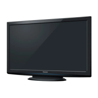
Do you have a question about the Panasonic TX-PR42G10 and is the answer not in the manual?

Summary

Safety Precautions

General Guidelines

General guidelines for servicing the equipment.

Touch-Current Check

Procedure for checking touch currents between exposed metallic parts.

Warning

Prevention of Electrostatic Discharge (ESD)

Techniques to prevent component damage from static discharge.

Service Mode

How to enter into Service Mode

Instructions on how to access the service mode.

Contents of adjustment mode

Details the adjustable parameters within the service mode.

Service tool mode

Steps to access the service tool mode.

Troubleshooting Guide

Check of the IIC bus lines

Procedure for checking IIC bus lines.

Power LED Blinking timing chart

Chart detailing power LED blinking patterns for troubleshooting.

No Power

Troubleshooting steps for scenarios where the unit has no power.

No Picture

Troubleshooting steps for when the unit displays no picture.

Disassembly and Assembly Instructions

Remove the Rear cover

Instructions to remove the rear cover of the unit.

Remove the P-Board

Procedure for removing the P-Board, with caution.

Component Removal

Remove the Tuner unit

Steps to remove the tuner unit.

Remove the A-Board

Procedure for removing the A-Board.

Board Removal

Remove the SU-Board

Procedure for removing the SU-Board.

Remove the SD-Board

Steps to remove the SD-Board.

Remove the SC-Board

Procedure for removing the SC-Board.

More Board Removal

Remove the SS2-Board

Steps to remove the SS2-Board.

Remove the SS-Board

Procedure for removing the SS-Board.

Remove the C1-Board

Steps to remove the C1-Board.

Final Board Removal

Remove the C2-Board

Procedure for removing the C2-Board.

Remove the Plasma panel section from the Cabinet assy (glass)

Instructions to remove the plasma panel section.

Remove the S-Board

Steps to remove the S-Board.

Remove the Front glass

Procedure for removing the front glass.

Panel and Board Replacement

Remove the GK-Board

Procedure for removing the GK-Board.

Replace the plasma panel

Instructions for replacing the plasma panel, including cautions.

Measurements and Adjustments

Adjustment Procedure

Steps for performing adjustment procedures.

Adjustment Procedures

Specific Adjustments

Block Diagram

Schematic Diagram

A-Board Schematics

More A-Board Schematics

C-Board Schematics

SC and SS-Board Schematics

SS-Board Schematics

Printed Circuit Board

More PCB Layouts

Exploded View and Replacement Parts List

Exploded View and Mechanical Replacement Parts List

Exploded views and mechanical parts list.

Electrical Replacement Parts List

Panasonic TX-PR42G10 Specifications

General IconGeneral
BrandPanasonic
ModelTX-PR42G10
CategoryPlasma TV
LanguageEnglish

Related product manuals