STEP
No.
Ref.
No.
PART REMOVE
NOTE
1
Section
No.
A B C D E F
How to read chart shown above:
A: Order of Procedure steps.
When reassembling, perform steps(s) in reverse order.
B: Ref No.
C: Part to be removed or installed.
D: Section No.
E: Identification of part to be removed, unhooked, unlocked,
released, unplugged, unclamped, or unsoldered.
F: Refer to "Notes in chart."
Section
No.
3
3
3
3
3
STEP
No.
Ref.
No.
PART REMOVE
NOTE
12
LCD Backlight
P.C.B.
LCD Case B
A B C D E F
3
5
4
4
3(L-4)
-
4(L-3)
3
-
LCD Case A Unit
33
2
3
FP8101
-
LCD Shaft Case
Unit
2(519), 2(546),
7(L-1)
E40
35
34
38
32
(533), (L-2),
FP8102
12
LCD Panel Ass'y
12
LCD Shield Plate
Unit
-----
-----
-----
-----
13
Diffusion Sheet
3
1
42
-----
13
LCD Panel
5
40
13
BEF Sheet
3
3
2
39
(L-5)
-----
13
Reflect Sheet
3
37
13
Lead Light Panel
3
6
41
13
BEF Sheet A
3
7
36
13
LCD Panel Holder
Unit
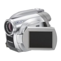
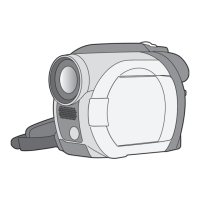
LCD PORTION
How to read chart shown above:
A: Order of Procedure steps.
When reassembling, perform steps(s) in reverse order.
B: Ref No.
C: Part to be removed or installed.
D: Section No.
E: Identification of part to be removed, unhooked, unlocked,
released, unplugged, unclamped, or unsoldered.
F: Refer to "Notes in chart."
STEP
No.
Ref.
No.
PART REMOVE
NOTE
2
Section
No.
A B C D E F
SIDE CASE R PORTION
3
11
Speaker
Side R/SD Ass'y
45
3
3
2(533),
Unsolder
11
Side R P.C.B.
1
3
11-
(408), (457)
2(533), (46)
E60
4
3
(533), (48)
11
Open Switch
P.C.B.
E61
 Loading...