Example 10
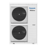
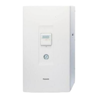
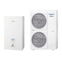
Heat pump cascade with hydraulic isolation of the heating circuits by means of buffer tank
Closed-loop control of cascade operation by means of an external controller,
taking into account operating time, redundancy and peak load.
CLOSE
OPEN
N
1 2 3 4 5 6
7 8
9 10 11 12
13 14
15 16
17 18
19 20
21
22 23
CLOSE
OPEN
CLOSE
OPEN
N
COOL
HEAT
N
L
N
MM
CLOSE
OPEN
N
1 2 3 4 5 6
7 8
9 10 11 12
13 14
15 16
17 18
19 20
21
22 23
CLOSE
OPEN
CLOSE
OPEN
N
COOL
HEAT
N
L
N
2
44
5
6
3
3
Schematic illustration – relevant standards
and guidelines must be observed!
2
Room thermostat
3
Outside temperature sensor
(integrated in the outdoor unit)
4
Control for heating circuit
mixer (building side)
5
Overriding control of the cascade
operation mode
6
Buffer tank
 Loading...
