Do you have a question about the Panasonic WH-SXC12F6E5 and is the answer not in the manual?
Explains WARNING, CAUTION, and PROHIBITED symbols for safety.
Covers critical safety rules for installation and servicing from item 1 to 18.
Covers specific WARNING points from 19 to 27 related to product usage and installation.
Details CAUTIONary points from 1 to 14 regarding potential damage or minor injury.
Details cooling and heating capacities, EER, and COP under test conditions.
Specifies noise levels, airflow, and operating conditions.
Information on refrigerant, oil, control device, compressor, fan, and heat exchanger.
Covers unit dimensions, weight, pipe sizes, and length limitations.
Highlights the use of inverter technology for energy efficiency.
Details high efficiency and use of R410A refrigerant for environmental protection.
Covers long installation piping, flexible piping, and easy-to-use control panel features.
Includes A-class pump, improved deice cycle, and protection features like auto-restart.
Describes features enhancing serviceability, such as self-diagnosis and maintenance design.
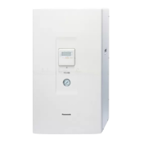
Identifies main components of the indoor unit with numbered references.
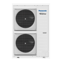
Identifies main components of the outdoor unit with lettered references.
Provides detailed dimensional drawings and measurements for the indoor unit.
Illustrates the refrigerant flow for cooling and heating cycles.
Shows the water flow within the system.
Details piping sizes, lengths, and refrigerant charge requirements.
Detailed schematic showing electrical connections for the indoor unit.
Detailed schematic showing electrical connections for the outdoor unit.
Step-by-step guide for adjusting water flow rate via service mode.
Interprets the Pressure-Flow rate graph for system performance.
Shows heating capacity and input power at various outdoor temperatures.
Shows cooling capacity and input power at various outdoor temperatures.
Details cooling capacity and input power with different indoor water inlet temperatures.
Displays cooling capacity and input power at elevated indoor water inlet temperatures.
Illustrates heating capacity and input power based on piping length.
Shows cooling capacity and input power as affected by piping length.
Presents heating capacity and input power data in tabular format for different models.
Presents cooling capacity and input power data in tabular format for different models.
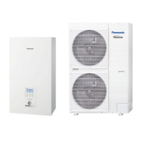
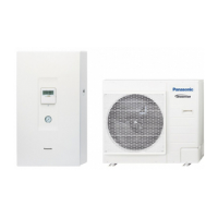
This document outlines the service manual for a Panasonic Air-to-Water Heatpump, specifically the Indoor Unit WH-SXC12F6E5 and Outdoor Unit WH-UX12FE5, destined for Europe. It provides crucial information for experienced repair technicians regarding the installation, servicing, and maintenance of the unit.
The Panasonic Air-to-Water Heatpump system is designed for both heating and cooling applications, utilizing an air-to-water heat exchange process. The system comprises an indoor unit (WH-SXC12F6E5) and an outdoor unit (WH-UX12FE5). The outdoor unit extracts heat from the ambient air (for heating) or expels heat to the ambient air (for cooling), while the indoor unit transfers this thermal energy to or from the water circuit, which can then be used for space heating, domestic hot water, or space cooling. The system incorporates inverter technology for energy saving and high efficiency, and uses R410A refrigerant, which is a non-ozone depleting substance.
The outdoor unit, WH-UX12FE5, has a cooling capacity of 10.00 kW (34100 BTU/h) and a heating capacity of 12.00 kW (41000 BTU/h) under specified conditions (EN 14511). Its Cooling EER is 2.81 W/W and Heating COP is 4.74 W/W (A35W7 condition). The noise level for the outdoor unit is 50 dB(A) for both cooling and heating, with a power level of 68 dB for cooling and 67 dB for heating. Airflow is 93.3 m³/min (3290 ft³/min) for cooling and 80.0 m³/min (2830 ft³/min) for heating. The unit uses 2.85 kg (100.6 oz) of R410A refrigerant and FV50S (1200) refrigeration oil. Dimensions are 1340 mm (52-3/4 inch) height, 900 mm (35-7/16 inch) width, and 320 mm (12-19/32 inch) depth, with a net weight of 101 kg (223 lbs). The compressor is a 3.0 kW brushless (4-poles) hermetic motor. The fan is a propeller type, PP material, DC (8-poles) motor with an input power of 60 W. Fan speeds are 600 rpm (top) and 640 rpm (bottom) for cooling, and 520 rpm (top) and 560 rpm (bottom) for heating. The heat exchanger uses aluminium (pre-coat) corrugated fins with a size of 903.7 x 1295.4 x 38.1 mm.
The indoor unit, WH-SXC12F6E5, has an operation range of 16-43°C outdoor ambient for cooling and -20-35°C for heating. Water outlet temperatures range from 5-20°C for cooling and 25-55°C for heating. The noise level is 33 dB(A) for cooling, with a power level of 46 dB. Dimensions are 892 mm (35-1/8 inch) height, 502 mm (19-3/4 inch) width, and 353 mm (13-29/32 inch) depth, with a net weight of 45 kg (99 lbs). Water pipe diameters are 28 mm (1-3/32 inch) for both inlet and outlet, and the water drain hose inner diameter is 15 mm (19/32 inch). The pump is a DC motor with 7 speeds (software selection) and an input power of 60 W. The hot water coil is a brazed plate type with 36 plates, measuring 65 x 120 x 376 mm. Water flow rates are 28.7 l/min (1.7 m³/h) for cooling and 34.4 l/min (2.1 m³/h) for heating. It includes a pressure relief valve (open at 300 kPa, close at 265 kPa and below) and a magnetic lead switch for flow detection. The integrated electric heater has a capacity of 6.00 kW. The expansion vessel has a volume of 10 liters and a MWP of 3 bar.
Piping specifications: Liquid pipe diameter is 9.52 mm (3/8 inch) and gas pipe diameter is 15.88 mm (5/8 inch). Standard piping length is 7 m (23.0 ft), with a range of 3 m (9.8 ft) to 30 m (98.4 ft). The maximum elevation difference between indoor and outdoor units is 20 m (65.6 ft). Additional refrigerant charge is 50 g/m (0.5 oz/ft) for lengths exceeding 10 m (32.8 ft).
The system offers an easy-to-use control panel with various modes including Auto mode, Holiday mode, Dry concrete function, and Weekly timer setting. The water pump speed can be adjusted via the control panel, allowing for optimization based on system requirements. The unit is designed for use in a closed portable water system, preventing excessive corrosion and bacterial growth.
The heat pump includes several serviceability features to aid technicians. These include a Breakdown Self Diagnosis function, System Status Check Buttons, and a System Pumpdown Button for servicing. The outdoor unit features a front maintenance design for easier access. The manual emphasizes the importance of using specified parts for replacement to prevent hazards and maintaining the original design. It also provides instructions for adjusting the water flow rate via a service mode, which is crucial for optimal system performance and efficiency. The P-Q graph in the manual helps technicians determine the available external static pressure in relation to the water flow rate, allowing for precise adjustments based on the hydraulic system's pressure loss. Regular checks for refrigerant gas leakage are advised to prevent toxic gas generation in case of fire.