EasyManua.ls Logo

Panasonic WH-SXC12H6E5 User Manual

Panasonic WH-SXC12H6E5
40 pages
To Next Page IconTo Next Page
Page #1 background imageLoading...
Page #1 background image
© Panasonic Corporation 2017.
Indoor Unit Outdoor Unit
WH-SXC09H3E5
WH-SXC12H6E5
WH-UX09HE5
WH-UX12HE5
Destination
Europe
WARNING
This service information is designed for experienced repair technicians only and is not designed for use by the general public.
It does not contain warnings or cautions to advise non-technical individuals of potential dangers in attempting to service a product.
Products powered by electricity should be serviced or repaired only by experienced professional technicians. Any attempt to
service or repair the products dealt with in this service information by anyone else could result in serious injury or death.
There are special components used in this equipment which are important for safety. These parts are marked by in the Schematic
Diagrams, Circuit Board Diagrams, Exploded Views and Replacement Parts List. It is essential that these critical parts should be
replaced with manufacturer’s specified parts to prevent shock, fire or other hazards. Do not modify the original design without permission
of manufacturer.
IMPORTANT SAFETY NOTICE
In order to avoid frostbite, be assured of no refrigerant leakage during the installation or repairing of refrigerant circuit.
PRECAUTION OF LOW TEMPERATURE
Question and Answer IconNeed help?

Do you have a question about the Panasonic WH-SXC12H6E5 and is the answer not in the manual?

Panasonic WH-SXC12H6E5 Specifications

General IconGeneral
BrandPanasonic
ModelWH-SXC12H6E5
CategoryHeat Pump
LanguageEnglish

Summary

Safety Information

General Warning

Important safety notice for service personnel regarding electrical hazards.

Important Safety Notice

Highlights critical safety components and precautions against shock, fire, or other hazards.

Low Temperature Precaution

Warning regarding frostbite from refrigerant leakage during installation or repair.

Product Features

Inverter Technology

Energy saving technology for efficient operation.

High Efficiency

Enhances performance and reduces energy consumption.

Environment Protection

Uses refrigerant with no ozone depletion.

Long Installation Piping

Allows for extended piping up to 30m with 20m height difference.

Easy to Use Control Panel

Offers modes like Auto, Holiday, Dry, and Weekly Timer.

Energy Efficient Pump

Features adjustable water pump speed via control panel.

Protection Features

Includes random auto restart and safety mechanisms.

Serviceability Features

Provides self-diagnosis and easy maintenance access.

Indoor Unit Dimensions

Detailed Unit Measurements

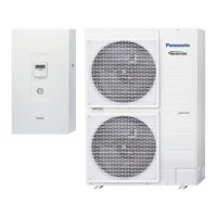
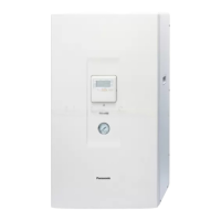
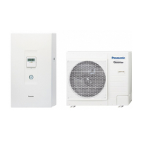
Provides detailed diagrams and measurements for the indoor unit.

Outdoor Unit Dimensions

Detailed Unit Measurements

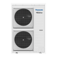
Provides detailed diagrams and measurements for the outdoor unit.

Refrigeration and Water Cycle Diagram

Refrigerant Piping Specifications

Details piping sizes, lengths, and additional refrigerant requirements.

Indoor Unit Wiring Diagram

Power Supply and Control Circuits

Details power distribution and control board connections.

Outdoor Unit Wiring Diagram

Component Wiring and Control Circuits

Illustrates wiring for outdoor unit components and control systems.

Indoor Unit Installation Procedures

Best Location Selection

Guidelines for choosing the optimal installation site for the indoor unit.

Wall Penetration and Piping Sleeve

Instructions for creating wall penetrations for piping.

Installation Plate Mounting

Procedures for securely mounting the installation plate.

Accessing Internal Components

Warning and steps for accessing internal parts.

Indoor Unit Installation Steps

Attaching the Indoor Unit

Steps for physically mounting the indoor unit onto the installation plate.

Water Piping Connection

Instructions for connecting the water circuit to the indoor unit.

Refrigerant Pipe Installation

Guidelines for connecting and tightening refrigerant pipes.

Piping and Drain Work

Cutting and Flaring Piping

Procedures for cutting and flaring refrigerant pipes.

Drain Elbow and Hose Installation

Instructions for installing the drain elbow and hose.

Pressure Relief Valve Drainage Pipework

Guidance on connecting the drain hose to the pressure relief valve.

Connecting The Cable To The Indoor Unit

Instructions for connecting electrical cables to the indoor unit.

Power Cord and Cable Fixing

Fixing of Power Supply Cord and Connecting Cable

Procedures for securing power and connecting cables.

Wire Stripping and Connecting Requirement

Guidelines for proper wire stripping and connection.

Connecting Requirements and Remote Controller

Connecting Requirements

Specifies electrical connection requirements and standards.

Remote Controller Installation Location

Guidance on where to install the remote controller for optimal performance.

Remote Controller Wiring

Instructions for wiring the remote controller to the indoor unit.

Remove The Remote Controller From Indoor Unit

Steps to detach the remote controller from the indoor unit.

Remote Controller Mounting and Water Charging

Mounting The Remote Controller

Instructions for installing the remote controller (exposed and embedded types).

Replace The Remote Controller Cover

Steps to replace the cover after removing the remote controller.

Charging The Water

Procedure for filling the system with water and purging air.

Water Charging Procedure

Setting Pressure Relief Valve

Step to set the pressure relief valve to the correct level.

Filling and Checking Water

Steps for filling the system with water and verifying operation.

External Device Connections

Connecting Optional Devices

Guidelines for connecting various optional external devices to the main PCB.

Tank Sensor Specifications

Details characteristics and cable requirements for tank sensors.

Optional PCB Connections

Connecting Optional PCB

Instructions for connecting to an optional PCB for zone control.

Terminal Screw Torque Specifications

Torque values for terminal screws on the PCB.

Cable Connections and Signal Inputs

Connecting Cables Length

Table specifying maximum cable lengths for external devices.

Connection of Optional PCB (CZ-NS4P)

Diagram showing connections to the optional CZ-NS4P PCB.

Signal Inputs

Details on signal inputs like thermostat, external control, and remote controller.

Recommended External Device Specifications

Sensor Specifications

Details on recommended sensors like room, solar, and outdoor temperature sensors.

Sensor Characteristic Table

Table showing resistance values for various sensors at different temperatures.

Optional Device Installation

Optional Pump Installation

Instructions for installing an optional pump.

Optional Mixing Valve Installation

Instructions for installing an optional mixing valve.

Network Adaptor Installation (Optional)

Steps for installing the network adaptor.

Outdoor Unit Installation Location

Best Location Selection

Guidelines for choosing the optimal installation site for the outdoor unit.

Piping Length and Refrigerant

Information on piping length and additional refrigerant requirements.

Outdoor Unit Installation

Installation Diagram

Diagram illustrating the outdoor unit installation layout and dimensions.

Fixing the Unit

Instructions for securely mounting the outdoor unit.

Disposal of Outdoor Unit Drain Water

Guidance on managing outdoor unit drain water.

Connecting The Piping

Connecting The Piping to Outdoor Unit

Instructions for connecting pipes to the outdoor unit.

Cutting and Flaring The Piping

Procedures for preparing and flaring pipes.

Evacuation Of The Equipment

Evacuation Procedure

Steps to remove air and moisture from the system.

Air-Tightness Test on the Refrigerating System

Procedures for testing the system for refrigerant leaks.

Refrigerant Leak Detection and Vacuum Test

Step 2: Refrigerant leak detection

Methods for detecting refrigerant leaks using detectors.

Step 3: Vacuum test

Procedures for performing a vacuum test on the system.

Connect The Cable To The Outdoor Unit

Connecting Cable Specification

Details on the required flexible cable for indoor/outdoor unit connection.

Cable Guiding and Fixing

Instructions for routing and securing the connecting cable.

Wire Stripping and Pipe Insulation

Wire Stripping and Connecting Requirement

Guidelines for preparing and connecting wires.

Pipe Insulation

Instructions for insulating pipe connection portions and drain hoses.

Pump Speed Settings

Maximum pump speed setting on remote control

How to adjust pump speed via the remote control.

P-Q graph for different pump HEX duty

Graph showing pump performance characteristics.

Heating Characteristics

Heating Performance at Different Outdoor Air Temperatures

Performance data for heating at various outdoor temperatures.

Cooling Characteristics

Cooling Performance at Different Outdoor Air Temperatures

Performance data for cooling at various outdoor temperatures.

Cooling Characteristics

Cooling Performance at Different Outdoor Air Temperatures

Performance data for cooling at various outdoor temperatures.

Cooling Characteristics

Cooling Performance at Different Outdoor Air Temperatures

Performance data for cooling at various outdoor temperatures.

Heating Characteristics

Heating Performance at Different Piping Lengths

Performance data for heating at various piping lengths.

Cooling Characteristics

Cooling Performance at Different Piping Lengths

Performance data for cooling at various piping lengths.

Performance Capacity Tables

Heating Capacity Table

Table detailing heating capacity and input power based on temperatures.

Cooling Capacity Table

Table detailing cooling capacity and input power based on temperatures.

Related product manuals