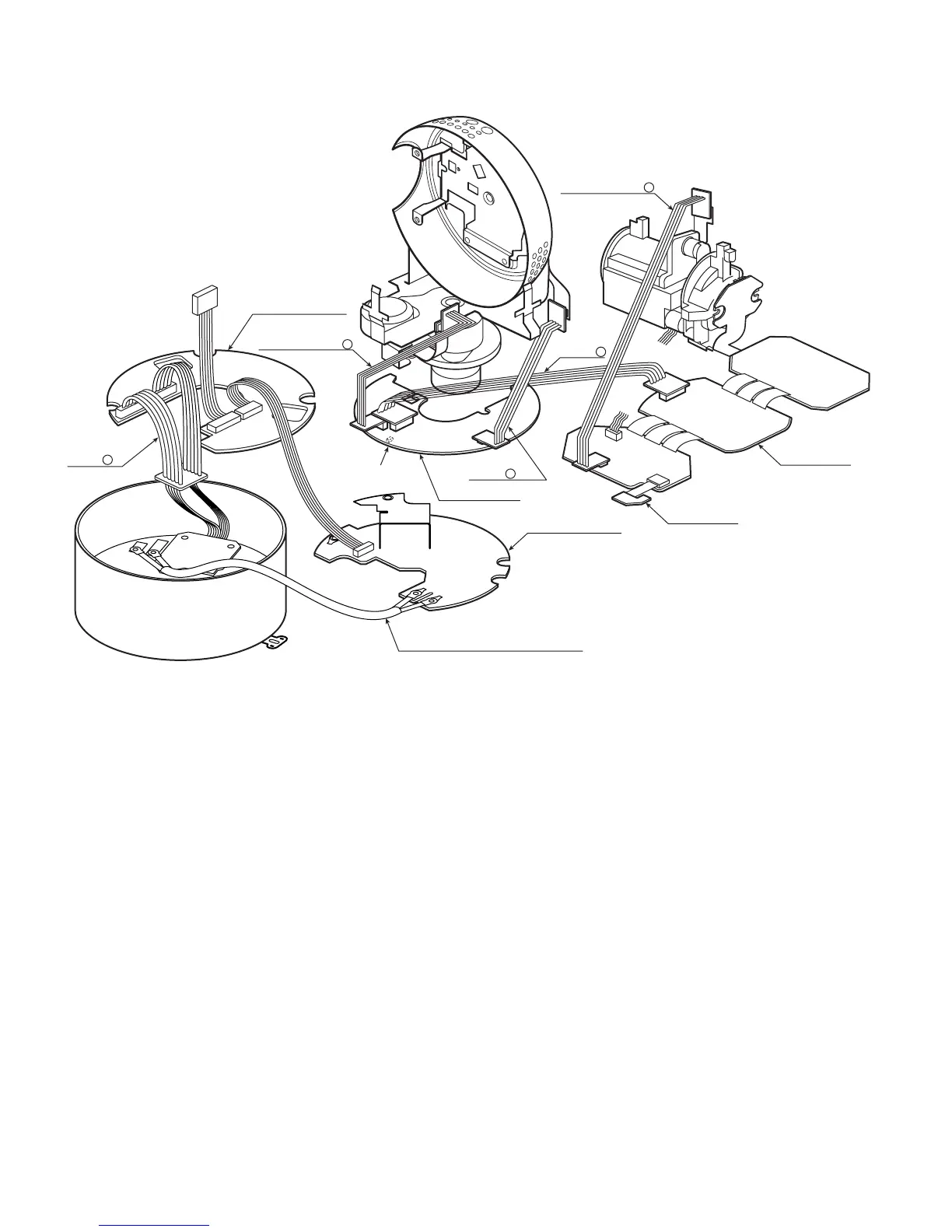
2.5. How to Connect the Extension Cables for Servicing
Fig. 2-5-1
8
Connect Extension Cable A between CN201 of the Main Board and the Lens.
8
Connect Extension Cable B between CN4 of the Main Board and CN1 of the Servo Board.
8
Connect Extension Cable C between CN5 of the Servo Board and the Pan Motor and between CN2 of the Servo Board and the
Tilt Motor.
8
Connect Extension Cable D between CN1 and CN2 of the Communication Board and the Base Unit.
8
Supply the power to WV-CS850B/CS854BE.
8
Contact the magnet to VS1 on the Servo Board.
 Loading...