3. Connection and Setting up for
Adjustment
3.1. Connection
8
Fig. 3-1-1 shows the connecting diagram for the
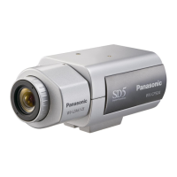
adjustment of the WV-CS850B/CS854BE.
Fig. 3-1-1
8
Connect the Underscanned Colour Video Monitor to the
Video Output Connector of the E.V.R. Adjustment Kit
through the Vectorscope using the coaxial cables.
8
Connect the Video Output Cable of the WV-
CS850B/CS854BE to the CAMERA INPUT Connector of
the E.V.R. Adjustment Kit by the coaxial cable.
8
Terminate the input terminal of the Underscanned Colour
Video Monitor with 75Ω.
8
Connect the 24V AC Power Supply Unit to the WV-
CS854B or connect the 220-240 V AC Power Supply Unit
to the WV-CS850B.
8
Connect the +12 V DC Power Supply Unit to the E.V.R.
Adjustment Kit.
8
Connect the E.V.R. Adjustment Kit to IBM PC/AT type
using the Standard Straight RS-232C cable.
8
Connect the probe of the Digital Voltmeter, Oscilloscope
or Frequency Counter at the desired Test Point in each
adjustment step.
3.2. Setting Up for the Remote E.V.R
Adjustment Kit
< Remote E.V.R Adjustment Kit >
8
Fig. 3-2-1 shows the Remote E.V.R. Adjustment Kit.
Fig. 3-2-1
< Switch Setting >
8
Referring to Fig. 3-2-2, remove four screws that secure
the Upper Cover and remove the Upper Cover.
Fig. 3-2-2
8
Set the switch SW3 on the board to the position as shown
in Fig. 3-2-3.
Fig. 3-2-3
8
Set the VP/STD CAMERA selection switch on the rear
panel to STD CAMERA position.
ON position.
Remove four screws.
STD. CAMERAVP CAMERA
 Loading...

