14/1/98 Page 21 Issue H
Fault Inhibit
This can be set to either enable or inhibit of all fault trips. Note that Thermal overload is always
enabled irrespective of this fault inhibit setting.
- Contactor Applications
In order to avoid the possibility of a contactor attempting to break a short-circuit current in excess of
its rating when this is the duty of the short circuit protective device e.g. HRC fuses, the facility is
provided to inhibit a fault trip above a set current level. This level should normally be no greater
than the rated short-circuit breaking capacity of the contactor, with allowance for a suitable safety
margin. The inhibit level can be selected in the range 400% to 1200% of In in steps of 100% by
setting the last 4 bits in the matrix below.
Example
To configure the relay such that pick up occurs at 1.1 x FLC with a fault inhibit above 900% In, then
the value set would be: 137
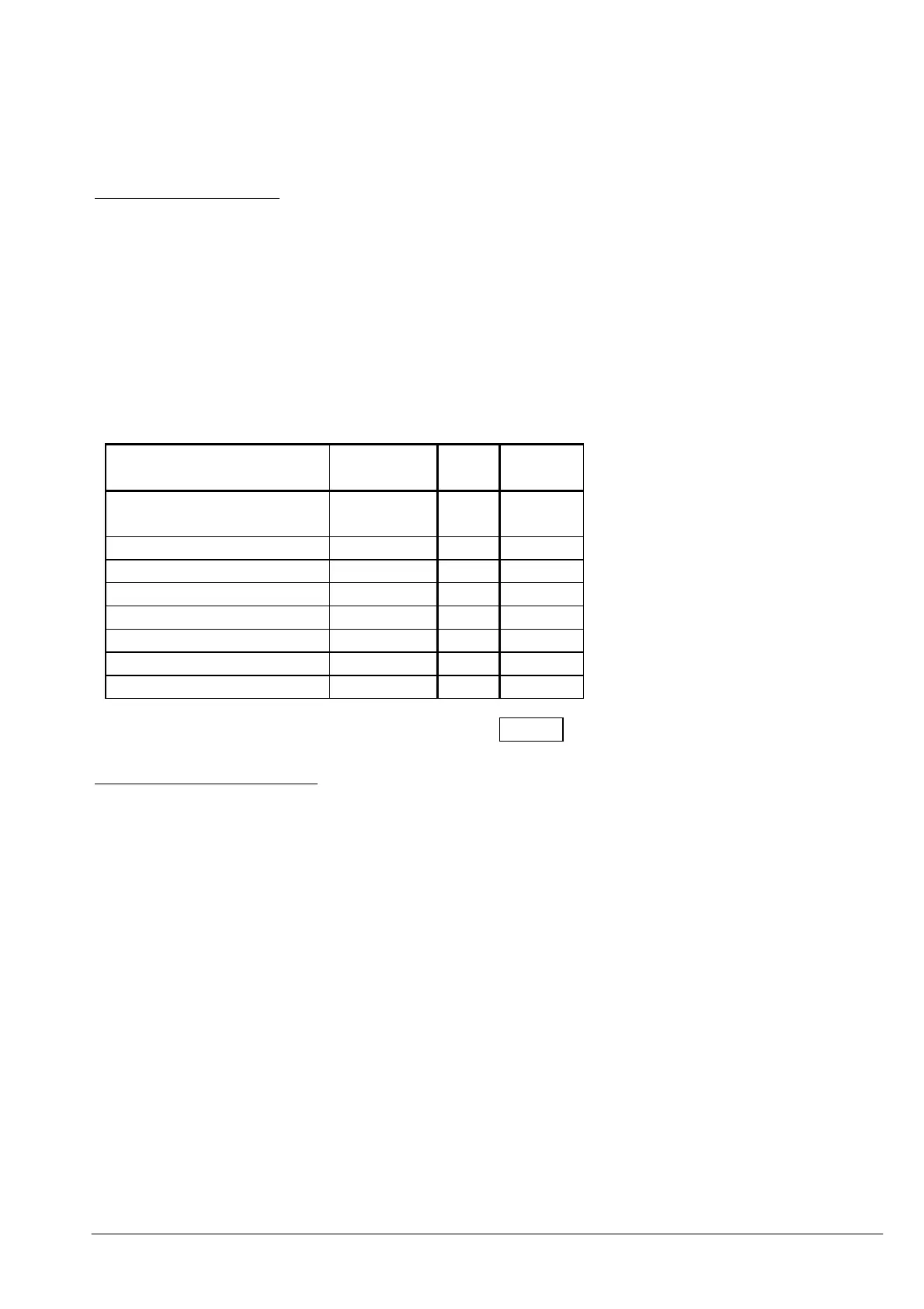
Action Numerical
Value
Set
Y/N
Value
Overload Pick-up Point
= 1.1 x FLC
128 Y 128
Reserved -
Reserved -
Reserved -
Fault Inhibit Value 800% 8 8
Fault Inhibit Value 400% 4 -
Fault Inhibit Value 200% 2 -
Fault Inhibit Value 100% 1 1
137
- Circuit breaker applications
For circuit-breaker controlled motors, the fault trips should be enabled and this is done by setting the
last 4 bits to the minimum value of 3.
Example
To configure the relay such that overload pick-up occurs at 1.05 x FLC with fault trips enabled for
circuit-breaker application, then the value set would be 003.